2200LZJE-HO-C6-N_2013.12.
Chapter 5 Maintenance
Compound 2-stage Screw Compressor 2016**C
5.7 Reassembly
5-44
5.7.5 Attaching Rotors (High/Low-stage)
<About Rotor Profiles of the 2016**C>
Regarding the products produced in and after November 1993, the profile has been changed from
A-profile to O-profile.
The most significant difference is the existence of the edge on the tooth tip. Edged A-profile has been
changed to the edgeless O-profile.
Make the rotor sufficiently adjusted. By using fine Emery paper, remove over any damage on the shaft
surface of the bearing and seal.
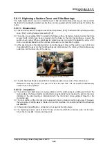
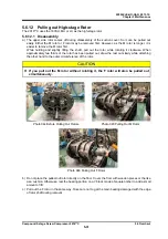
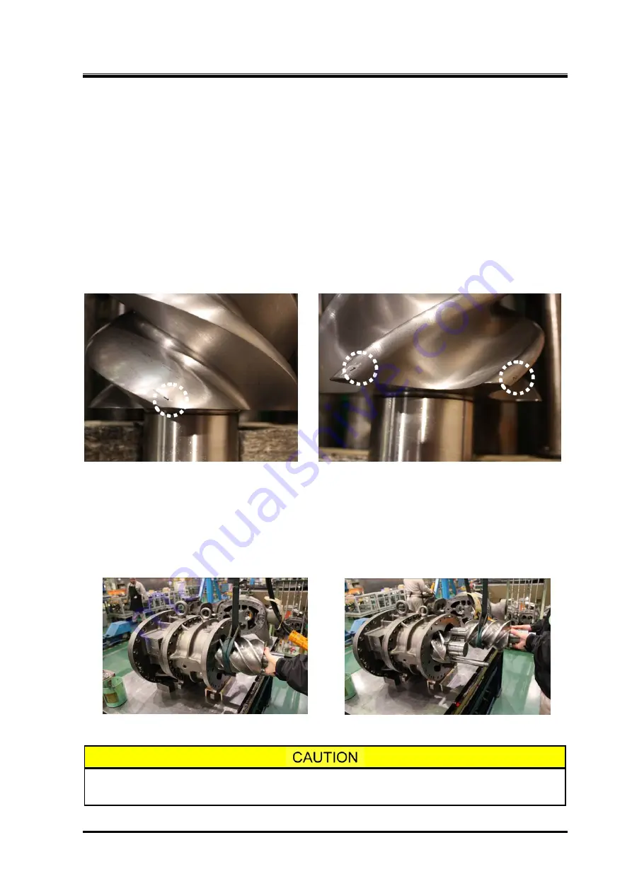
Both the M and F rotors have certain engagement positions which are indicated by stamp marks.
To facilitate the alignment when attaching to the rotor casing, numbers are stamped on the
discharge-side tooth peak of the M rotor and the suction-side tooth peak of the F rotor, respectively.
Photo 066 M Rotor Mating Mark Photo 067 F Rotor Mating Marks
a) Sufficiently lubricate the main bearing inside the bearing head as well as the bearing portion of the
rotor shaft.
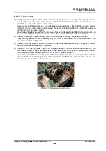
b) In assembly, attach the F rotor first to the casing.
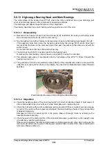
c) Insert the M rotor tooth peak (1) between the F rotor tooth peaks (1) and (2). To avoid problems
related to engagement and balance, etc., be sure to mate as shown above.
As the M rotor has a stamped mark on the discharge side, it can be easily aligned for assembly.
Photo 068 Attaching F Rotor Photo 069 Attaching M Rotor
In this state, the rotor's outer periphery is in contact with the rotor casing. Do not
rotate it much. Letting it rotate may cause its tooth tips to get worn.

