2200LZJE-HO-C6-N_2013.12.
Chapter 5 Maintenance
Compound 2-stage Screw Compressor 2016**C
5.7 Reassembly
5-47
d) Slide the suction cover on the surface plate, and move it to the assembly position. When fitting the
side bearing and the rotor shaft, be careful not to let the end of the rotor shaft damage the metal on
the inner surface of the side bearing.
e) When the rotor shaft fits in the side bearing, slide the suction cover parallel with the shaft for
assembly. Note that there is unloader push rod in the high-stage of the 2016**C.
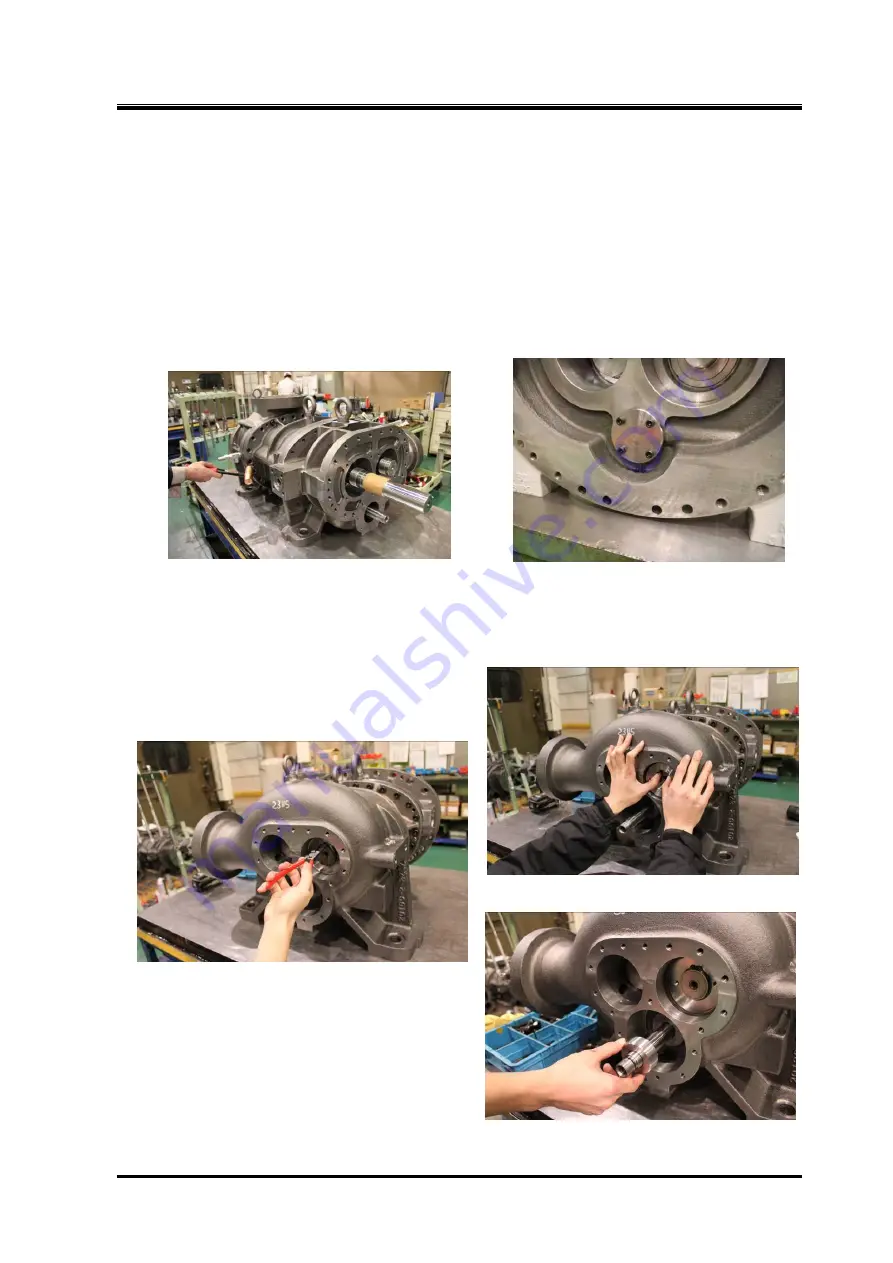
f) First, hammer two alignment pins for positioning. Then, fasten the bolts evenly.
The bolts (approximately 6 in quantity) on the lower side should be fastened
during final assembly,
placed on the special table
which was used during disassembly.
g) Rotate the M rotor shaft with your hand, and check the rotors mating condition.
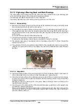
h) For the low-stage, attach the oil injection pipe
【
85
】
and then fasten it by using the oil injection pipe
retainer
【
164
】
.
Photo 082 Driving In Alignment Pin for Positioning Photo 083 Oil Injection Pipe Retainer
i) Move the push rod with your hand, and check the movement of the unloader slide valve.
j) While holding the M rotor shaft with your hand, move it in the axial direction and check that there is
allowance in the axial direction.
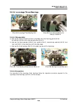
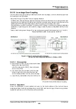
k) To the high-stage, attach the balance piston
【
30
】
and secure it with the stop ring
【
32
】
.
Check that the stop ring fits well in the groove.
Photo 084 Attaching the Balance Piston
Photo 085 Attaching the Stop Ring
m
)
Attach the load capacity adjustment spacer
(spacer for 20% load)
【
420
】
to the high-stage
push rod.
Photo 086 Attaching Load Capacity Adjustment Spacer
(Spacer for 20% Load)


