2200LZJE-HO-C6-N_2013.12.
Chapter 5 Maintenance
Compound 2-stage Screw Compressor 2016**C
5.7 Reassembly
5-49
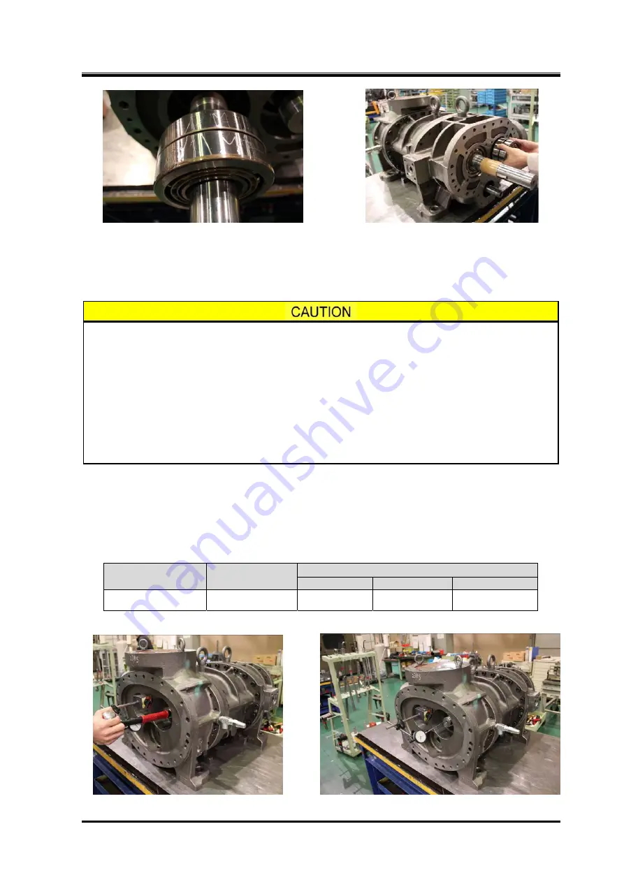
Photo 087 Thrust Bearing Assembly Mark Photo 088 Attaching Thrust Bearing
b) After attaching the thrust bearing, attach the thrust washer, lock washer and torsional slip washer.
Fasten the lock nut with the specified torque or tightening angle range (see Chapter 7 "7.3
Tightening Torques for Bolts and Nuts" in this manual), so that the inner ring of the thrust bearing is
fit in the rotor shaft.
Since the inner ring of the thrust bearing is clearance-fitted for ease of access at
the assembly site and is secured by the tightening force of the nut alone, the
tightening work is very important!
If the thrust bearing has been replaced, the difference between the bearing inner
ring and outer ring surfaces will be different even when the parts are
manufactured within standard values. Therefore, fully tightening the nut from the
initial use may lead to a noticeable reduction in the life of bearing, due to a lack of
end clearance between the rotor and the bearing head discharge end face, and
also due to indentations on the contact surface formed by ball pressure. To avoid
this, check for end clearance while tightening.
5.7.7.1 End Clearance Measurement
At this moment, measure the end clearance on the discharge side of the fully assembled rotor.
In particular, when the thrust bearing has been replaced, the end clearance must be measured. Even
when the same bearing is used, measure the end clearance for confirmation.
If the clearance does not fall within the specified range shown in Table 5-10, adjustment is needed.
Table 5-10 End Clearance (Unit : mm)
Model of the
compressor
High-stage
Low-stage
S
M
L
2016**C
0.04 to 0.05
0.26 to 0.30
0.28 to 0.32
0.31 to 0.35
■
End clearance of 2016**C is the same as A-profile rotor and O-profile rotor.
Photo 089 Pushing Rotor from Suction Side Photo 090 End Clearance Measurement


