2201Q4JE-MY-C9-N_2018.01.
Chapter 2 Compressor Specifications and Structure
Compound 2-stage Screw Compressor 4032**C
2.1 Overview of MYCOM 4032**C
2-1
Chapter 2 Compressor Specifications and Structure
2.1
Overview of
4032**C
The 2-stage compression system, which has hitherto required two units of standard-type screw
compressor for its embodiment, can now be realized by a single unit of compound 2-stage screw
compressor.
Generally, screw compressors use oil injection to keep discharge temperature at a low level during
operation without loss of volumetric efficiency even at high compression ratios. It can, therefore, be
operated with a single-stage compression system even at evaporative temperatures near -40
°
C.
However, for normal use at low temperatures, a 2-stage compression system is applied in order to
improve kW/RT (ratio of power consumption versus refrigerating capacity). If the 2-stage compression
system is configured with standard-type screw compressors, at least two screw compressor units need
to be installed, one on the high-stage and the other on the low-stage, which inevitably requires double
installation of the entire system including machinery, motors, utilities, etc.
This 2-stage screw compressor is produced to solve this problem. It is a single unit that has two
single-stage compressor units combined into one.
The 4032**C model is currently the biggest size compressor in the compound 2-stage
compressor C-series. In addition to general refrigeration systems and air conditioning systems, the
4032**C model has been used in variety process gas compression systems due to the ability to meet
various requirements specifications, i.e., temperature conditions, pressure conditions, power conditions,
etc. As a result, most of the products which have been manufactured and shipped until now, are special
specification products.
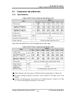
If there are different points of specifications between your purchased compressor and the standard
specification compressor described in this manual, refer to the document showing specifications of your
purchased compressor.
2.2
Model Designation of the Compressor
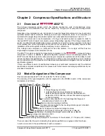
This manual describes 4032**C-*B*-51 and 4032**C-*B*-61 models.
The meaning of the type designation, which is engraved on the MODEL column of the compressor
nameplate, is as follows.
*
4032
**
C
-
*
B
*
-
51/61
5: Power frequency (6: 60Hz)
1: Indicates that it is a motor directly connected type.
* Unless specifically specified, machines manufactured in
September, 2010 or after do not have this indication engraved
on their nameplate.
Vi (volume ratio) specified for the high-stage discharge port,
standard value of which is
L
or
M
Means a booster (low-stage machine)
Vi (volume ratio) specified for the low-stage discharge port, standard
value of which is
L
or
M
Stands for Compound (compound 2-stage machine)
Specifications of high-stage rotor length, which is
LL
,
L
,
M
or
S
Specifications of low-stage rotor length, which is
XL
,
LL
,
L,
M
or
S
High-stage rotor diameter of 320
Low-stage rotor diameter of 400
Indicates working fluid (Example: N = Ammonia, F= Fluorocarbon, P = Propane, HE = Helium)
There are cases that the symbol indicating the special specification is engraved other than these.
In such a case, refer to the specifications of each compressor.

