2201Q4JE-MY-C9-N_2018.01.
Chapter 2 Compressor Specifications and Structure
Compound 2-stage Screw Compressor 4032**C
2.3
Compressor Specifications
2-2
2.3
Compressor Specifications
2.3.1 Specifications
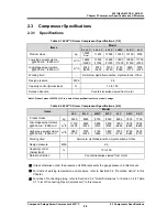
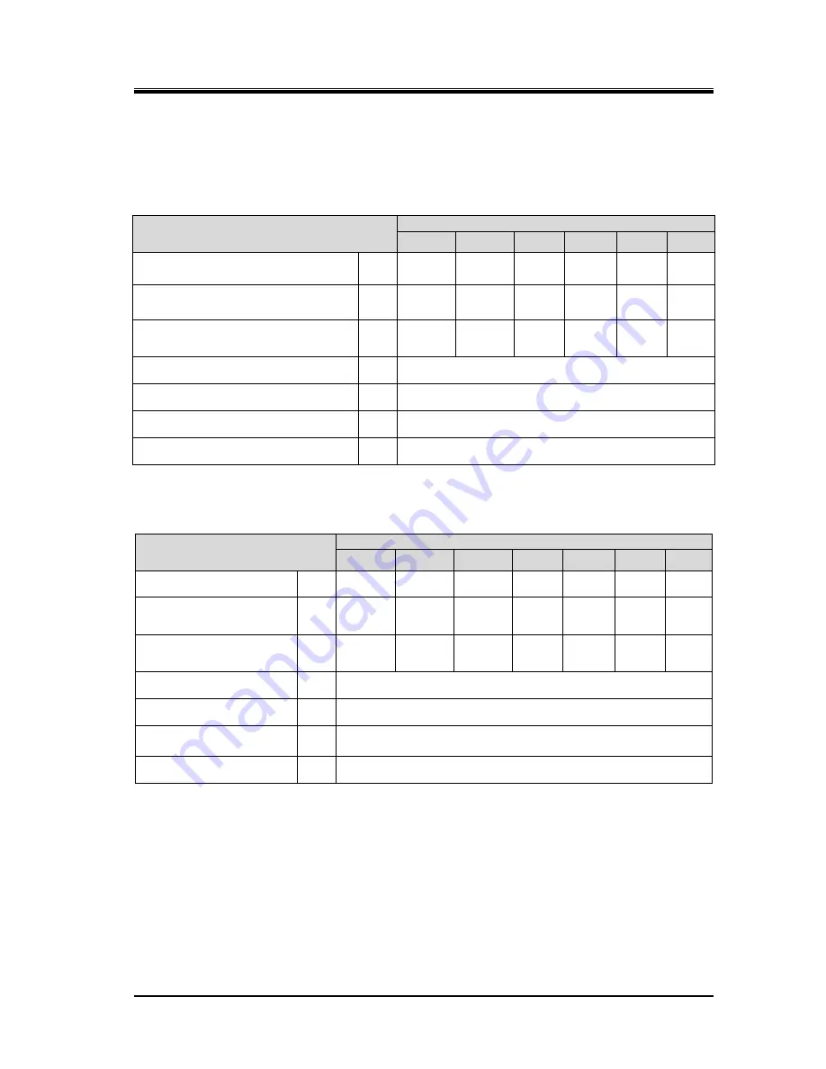
Table 2-1 4032**C Screw Compressor Specifications (1/2)
Items
Model
X L L L C L L L L C L L L C L L M C L L S C
L L C
Product mass
kg
12320
*Note1
11250
10500
10350
10150
9700
Low-stage swept volume
@3550 min
-1
/2950 min
-1
m
3
/h
15600
/12900
13800
/11500
13800
/11500
13800
/11500
13800
/11500
11700
/9700
High-stage swept volume
@3550 min
-1
/2950 min
-1
m
3
/h
6740
/5600
6740
/5600
5700
/4740
4760
/3960
3820
/3170
5700
/4740
Working fluid
-
Ammonia, Hydrofluorocarbon, Hydrocarbons, Other.
Design pressure
MPa
2.6
Capacity control (Actual load)
%
10 to 100
Rotation direction
-
Counterclockwise viewed from motor
*Note1: Product mass of 4032XLLLC is a data of the specifications for cast steel casings.
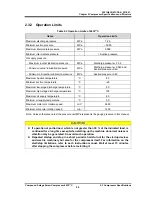
Table 2-2 4032**C Screw Compressor Specifications (2/2)
Items
Model
L S C
M L C
M M C
M S C
S L C
S M C
S S C
Product mass
kg
9350
8900
8750
8550
8050
7900
7700
Low-stage swept volume
@3550 min
-1
/2950 min
-1
m
3
/h
11700
/9700
9800
/8140
9800
/8140
9800
/8140
7800
/6480
7800
/6480
7800
/6480
High-stage swept volume
@3550 min
-1
/2950 min
-1
m
3
/h
3820
/3170
5700
/4740
4760
/3960
3820
/3170
5700
/4740
4760
/3960
3820
/3170
Working fluid
-
Ammonia, Hydrofluorocarbon, Hydrocarbons, Other.
Design pressure
MPa
2.6
Capacity control
(Actual load)
%
10 to 100
Rotation direction
-
Counterclockwise viewed from motor
Unless otherwise noted, the pressure unit MPa represents the gauge pressure in this manual.
For limits of working temperature and pressure, refer to Section2.3.2 "Operation Limits" in this
Chapter.
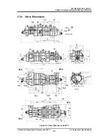
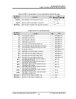
For sizes of connecting piping, refer to Section 2.3.2 "Outer Dimensions" or Section 3..2.4 Table
3-1 " List of Connecting Pipes (Compressor)" in this manual.

