2201Q4JE-MY-C9-N_2018.01.
Chapter 5 Maintenance and Inspection
Compound 2-stage Screw Compressor 4032**C
5.4 Disassembly and Inspection
5-16
5.4.2
Unloader Cover
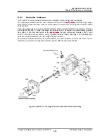
The unloader cover [74-1] [74-2] is mounted with the indicator cam [77-1] [77-2], which converts the
linear motion of the unloader slide valve to a rotational motion, and their mounting parts.
The indicator cam is supported by the ball bearing [78-1] [78-2] and fixed to the cover with a bearing
gland [80-1] [80-2].
To make it airtight, the V-ring [82-1] [82-2], spring [83-1] [83-2], and spring retainer [84-1] [84-2] are also
attached.
The indicator cam has a spiral groove of 340° to cover the moving range of the unloader slide valve.
The indicator cam shaft is rotated being pushed by the guide pin [68-1] [68-2] on the top end of the
unloader push rod [67-1] [67-2].
This block structure of the low-stage and the high-stage is the same, but there is only one different point
that the low-stage hexagon socket head cap screw [81-1] which fastens the bearing gland [80-1]
requires the spring washer [597].
[Low-stage] [High-stage]
Figure 5-5 Unloader Cover Block
5.4.2.1
Disassembly
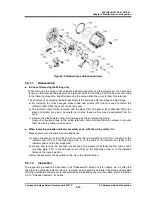
a) Unscrew and remove the unloader cover mounting hexagon socket head cap screws [76-1] [76-2].
b) Pull the unloader cover with the indicator cam assembly out in the direction parallel to the axis of
the push rod in the unloader cylinder.
Carefully pull it straight, because if the unloader cover is pulled sideways, the shaft of the indicator
cam may be bent.
●
The mass of unloader cover assembly is approximately 16kg for the high-stage and
approximately 20kg for the low-stage. Because the indicator cam is long, firmly hold
the unloader cover assembly until it is completely pulled out from the unloader push
rod. Carelessly handling the unloader cover assembly may cause the injury.


