2201Q4JE-MY-C9-N_2018.01.
Chapter 5 Maintenance and Inspection
Compound 2-stage Screw Compressor 4032**C
5.4 Disassembly and Inspection
5-17
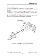
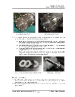
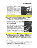
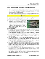
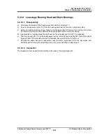
Low-stage Unloader Cover High-stage Unloader Cover
c) If the indicator cam will not move normally, check the spiral groove of the indicator cam, ball
bearing , and guide pin. The disassembly sequence is as follows:
c-1) As the bearing gland [80-1] [80-2], which fixes the indicator cam in place, is secured by
three hexagon socket head cap screws [81-1] [81-2] on the cylinder side of the unloader
cover, unscrew and remove these bolts.
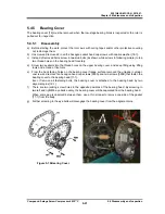
c-2) Then, the indicator cam can be pulled out with the ball bearing [78-1] [78-2] and the snap
ring (retaining ring) [79-1] [79-2] attached to the shaft.
c-3) Inside the unloader cover, the spring retainer [84-1] [84-2], spring [83-1] [83-2], and then
V-ring [82-1] [82-2] are assembled in this order.
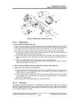
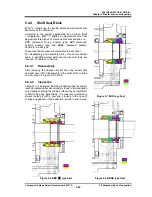
Because the V-ring is tightly engaged with the bore of the unloader cover, the lip of the
V-ring will be damaged when it is once removed, making it unusable again. Therefore, be
sure to replace it with a new one once it is disassembled.
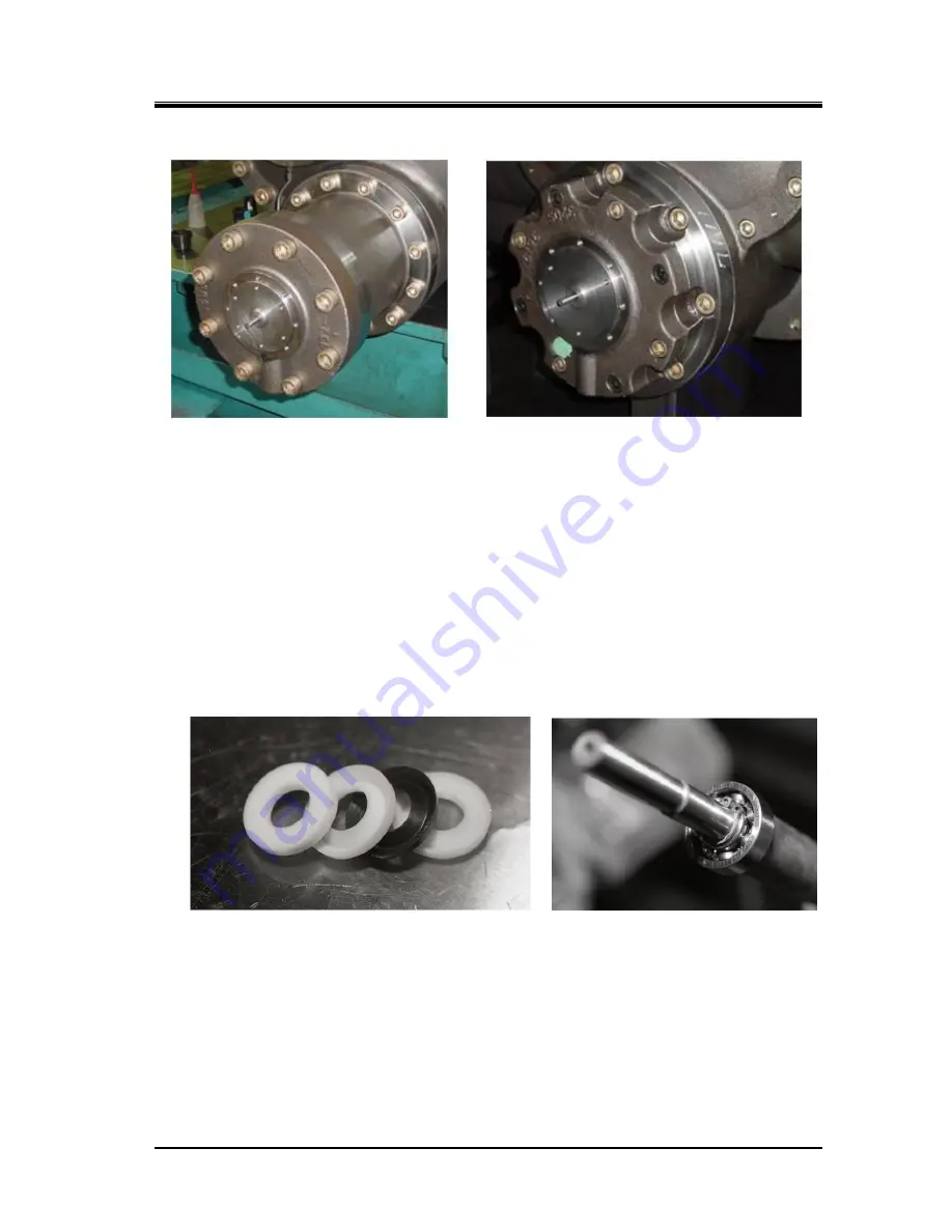
V-ring (Black colored Part material is NBR or FKM) Ball Bearing, Indicator Cam
5.4.2.2
Inspection
a) Check the packing of the indicator cam shaft for any flaw. If the refrigerant leaks without any flaw
observed in this part, it should be due to a defect of the V-ring or installing the V-ring without
sufficient oil. In this case, replace the V-ring.
b) Check the spiral groove of the indicator cam. If an abnormal flaw or wear is observed, replace it
with a new one.

