2201Q4JE-MY-C9-N_2018.01.
Chapter 5 Maintenance and Inspection
Compound 2-stage Screw Compressor 4032**C
5.4 Disassembly and Inspection
5-24
5.4.9
Low-stage Suction Cover and Side Bearings
If the work sequence is such that the thrust bearing block is disassembled first and then the suction
cover is removed, there is a risk that, when the suction cover is separated from the main rotor casing,
the rotor may also be pull out and dropped. As such, in the procedure described in this manual, the
suction cover is removed first, and then the thrust bearing is disassembled.
In this procedure to remove the suction cover before disassembling the thrust bearing
block, it is necessary to sufficiently loosen the lock nut that are securing the thrust
bearing while the rotor is supported by both the main and side bearings, in order not to
damage the rotor during the disassembly process.
5.4.9.1
Disassembly
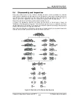
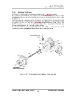
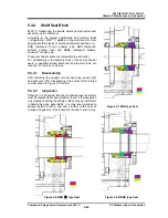
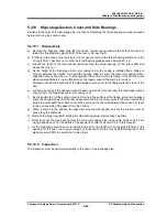
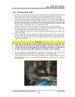
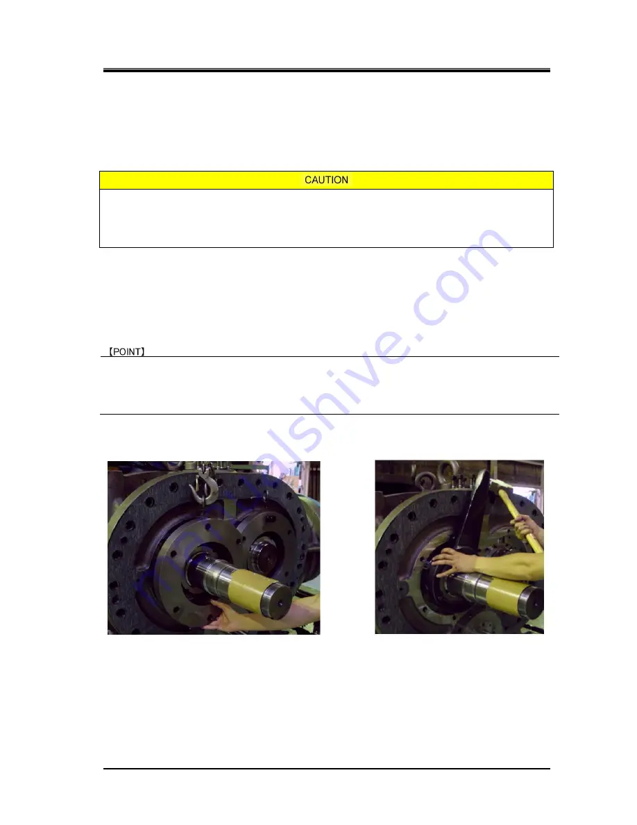
a) Screw in two eye bolts to the threaded holes on upper part of low-stage thrust bearing glands
[43-1A] [43-1B], then hook and lift them using crane or like lifting tools.
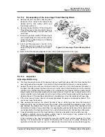
b) Remove the hexagon head bolts [45-1] with spring washers [46-1] fastening the thrust bearing
gland [43-1], and then remove the O-ring [150-1] and thrust bearing gland.
The thrust bearing gland may not be removed by pulling only your hands due to the O-ring [150-1] stuck
with the thrust bearing gland. In such a case, insert a flat blade screw driver or the like to the gap between
the thrust bearing gland and the bearing head, and slightly pull it toward you. The thrust bearing will come
off.
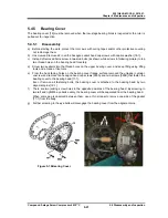
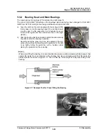
c) Unbend the tooth of the lock washers [40-1], and loosen the lock nuts [39-1] on both M rotor side
and F rotor side using a lock nut wrench.
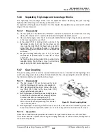
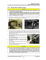
d) Hook up the eyebolts of the low-stage suction cover to the lifting tools of a crane or the like, and
then loosen and remove the hexagon socket head cap screws [2-1] securing the suction cover
[5-1] to the low-stage main rotor casing [1-1].
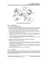
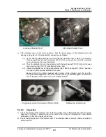
e) Drive in the alignment pins [3-1] to the main rotor casing side. If it is not feasible, screw in suitable
bolts to the jacking screw holes on the flange to push the suction cover evenly.
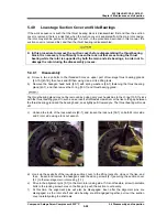
f) At this time, the alignment pins will also be disengaged. Even after the alignment pins are
disengaged, as the rotor shaft and side bearing are still engaged together, pull out the suction
cover carefully along the shaft axis.

