2201Q4JE-MY-C9-N_2018.01.
Chapter 5 Maintenance and Inspection
Compound 2-stage Screw Compressor 4032**C
5.4 Disassembly and Inspection
5-26
5.410 High-stage Suction Cover and Side Bearings
Similarly to the case of the low-stage side, the lock nut fastening the thrust bearing must be loosened
before removing the suction cover.
5.4.10.1 Disassembly
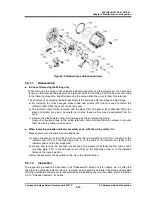
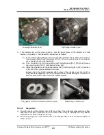
a) Remove the hexagon head bolts [45-2] and the conical spring washers [46-2] that are used to
fasten the thrust bearing gland [43-2]. Take care not to lose them.
b) Similarly to the case of the low-stage, it is not easy to remove the thrust bearing gland due to the
O-ring [150-2]. Take care not to drop the thrust bearing gland because it weighs 11 kg..
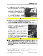
c) Unbend the tooth of the lock washer [40-2] securing the thrust bearing on the rotor shaft, and
loosen the lock nut.
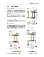
d) As the height of the high-stage main rotor casing is low, the casing is installed like a bridge to
connect between the suction cover and the bearing head. As such, the main rotor casing will be
supported only by one side (i.e., overhang) when the suction cover is removed. To avoid this, either
place squared timbers or use a lifting device to properly support the main rotor casing.
Moreover, hook up the eyebolts of the high-stage suction cover to the lifting tools of a crane or the
like.
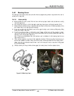
e) Loosen and remove the hexagon socket head cap screws [2-2] securing the high-stage suction
cover [5-2] to the high-stage main rotor casing [1-2].
f) As the gasket [6-2] of the suction cover is sticking to the surface of the flange, screw two hexagon
socket head cap screws [2-2] that have been removed into the screw holes in the main rotor casing
flange to evenly push the suction cover. When some gap is observed between them, use a scraper
to remove one side of the gasket from the surface.
g) When it comes to the position the alignment pins are disengaged, pull out the suction cover at
once along the shaft axis.
h) Remove the snap ring [29-2] holding the side bearing using internal snap ring pliers.
i)
Either push out the side bearing from the main rotor casing side using some block or pull it out
using a special tool. For the details of the special tool, refer to Section 5.5.2 in this manual..
j)
As the high-stage suction cover is installed with an O-ring [328] and O-ring gland [326-2] in the
opening for the push rod to pass through, remove them. As the four bolts fastening the O-ring
gland are small (M5), be careful not to lose them.
5.4.10.2 Inspection
The inspection must be performed similarly to the case of the low-stage side.

