2201Q4JE-MY-C9-N_2018.01.
Chapter 5 Maintenance and Inspection
Compound 2-stage Screw Compressor
4032**C
5.5 Reassembly
5-40
5.5.5 Suction Cover and Side Bearings
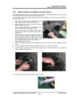
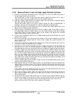
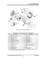
Similarly to the main bearing, the side bearing (O-ring type) [28] is machined to the size that will allow
light press fitting to the suction cover [5].
In addition as is the case with the O-ring for the main bearing, the size of the O-ring for the low-stage
side bearing has been changed to JIS B 2401 G200 from G210 according to the design modification.
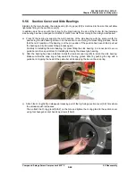
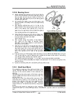
a) Press fit the bearing by aligning the notch position of the side bearing with the spring pin [8] for
positioning the side bearing driven-in on the suction cover. During the press fitting process, check
that the notch position of the bearing is at the pin position. If the position has been shifted, pull out
the bearing and try the press fitting process again.
Similarly to installing the main bearing, for press fitting the side bearing, it is convenient to use a
guide bar and/or a special tool for installing/removing the sleeve type bearing.
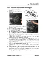
b) After the bearing has been installed, install the internal snap ring [29] to retain the side bearing.
Make sure that the snap ring is fully seated in the ring groove either by pushing the ring with a
guide bar or tapping the head of the guide bar while applying the bar on the snap ring.
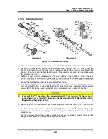
c) Attach the O-ring [328] on stepped processing part of the high-stage suction cover [5-2] hole where
the unloader push rod passes.
Then, attach the O-ring gland [326-2] on the hole and tighten the O-ring gland to the suction cover
using four hexagon socket head cap screws [166-2].

