2201Q4JE-MY-C9-N_2018.01.
Chapter 5 Maintenance and Inspection
Compound 2-stage Screw Compressor
4032**C
5.5 Reassembly
5-44
5.5.8.1 High-stage Block
As described in Section 5.4.11, for the high-stage thrust bearings, two types of bearings, i.e. the ball
bearing and the tilting pad thrust bearing, is used according to the working fluid, requirements of the
use of the package unit and the applicable standard. This section describes the ball bearing
specifications.
In the case of the tilting pad thrust bearing specifications on the high-stage thrust bearing block, refer to
next Section "Low-stage Block". The thrust bearing alignment spacer [42-2] and the thrust bearing
gland [43-2] are different from the ball bearing specifications.
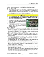
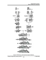
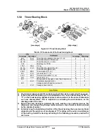
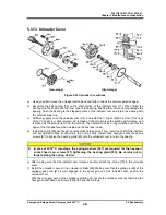
The assembly sequence for this part is as illustrated in Figure
5-20. The important points to be noted in the procedure are
described below:
a) Check the marking of either "M" or "F" on the thrust
bearing alignment spacer to ensure that the units are
assembled in the same combination of parts.
The front and back of the thrust bearing alignment
spacer must be distinguished when it is installed. The
larger chamfering side is on the machine side, and the
smaller chamfering side is on the thrust bearing side.
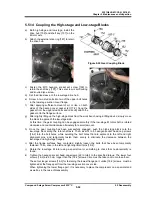
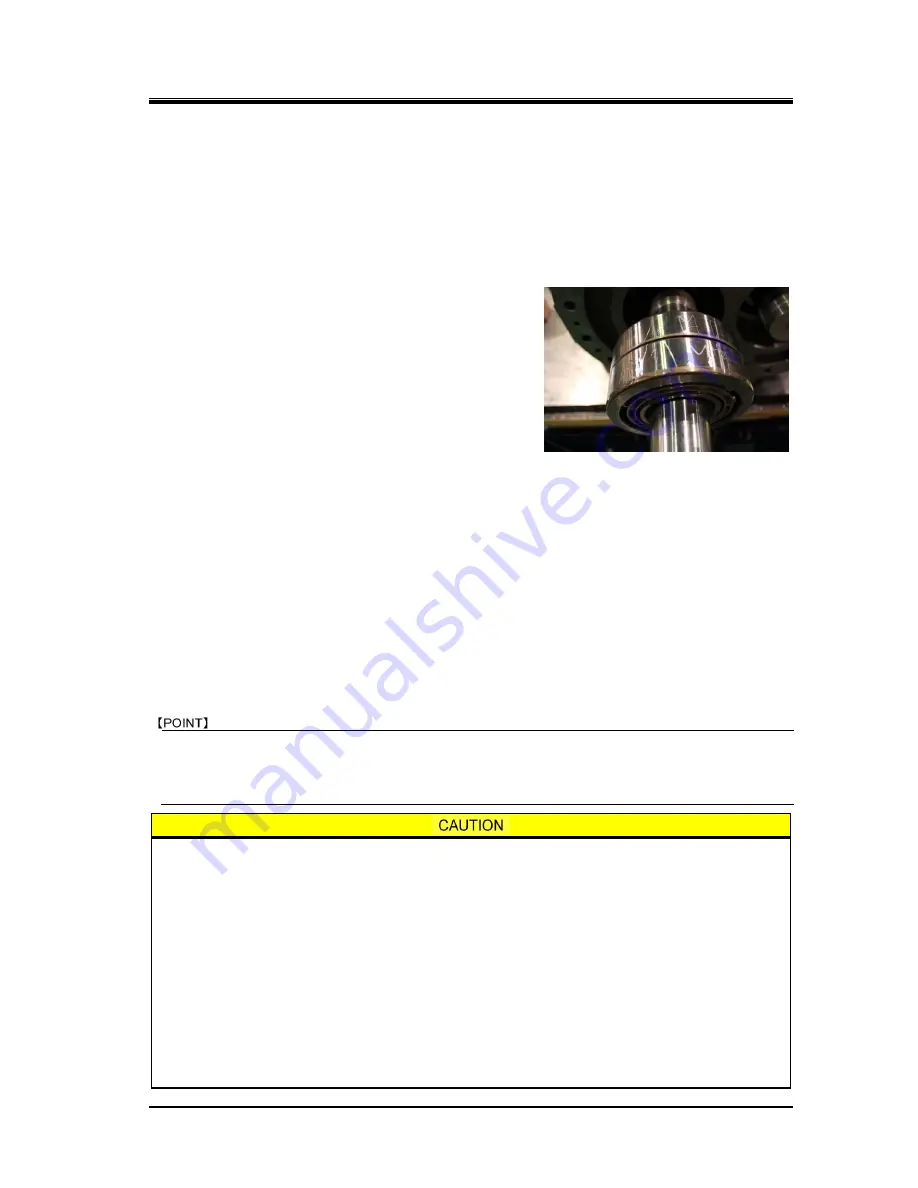
b) If thrust bearing has a "V" marking on the outer circumference, it means that the installation
direction of the bearing will sensitively affect the end clearance adjustment. In this case, the
bearing must be installed with the pointed end of the marking pointed toward the inside of the
machine.
If there is no "V" marking, it means that the direction of the bearing installation will not affect the
end clearance adjustment. However, in order to clearly determine the orientation (whether it is on
the inside or outside of the machine), first combine both bearings with the bearing number carving
facing the outside of the machine. Then, use a blue whetstone to write the above "V" marking on
the bearing to show the inside direction of the machine. Then, install the bearing (above picture).
c) After the thrust bearing has been installed, attach the thrust washer [250-2], lock washer [40-2],
and torsional slip washer [237-2]. Then, tighten the lock nut at the specified range of the tightening
angle (refer to Chapter 7, Section 7.3 "Tightening Torques for Bolts and Nuts" in this manual) to
secure the inner race of the thrust bearing on the rotor shaft.
This specified range of lock nut tightening angle is the same as the ball bearing specifications and
the TPTB specifications.
Tightening the lock nut while keeping the setting position between the lock nut wrench hooks and the
lock nut grooves may cause to make the rotor run-out to enlarge due to uneven tightening forces.
Change the setting position between the lock nut wrench hooks and lock nut grooves about four
times when fastening the lock nut.
As clearance fit is used for the inner race of the thrust bearing, this tightening work is
very important because the bearing is secured only by the tightening force of the
lock nut.
When the thrust bearing has been replaced, the dimensional difference between the
sides of the inner race and outer race varies even if it is within the tolerance of the
applicable standard specification. As such, if the thickness of the thrust bearing
alignment spacer that has been used is insufficient, and if the lock nut is securely
tightened from the first, the end clearance between the rotor shaft end and the end
face of the discharge side bearing head will be lost. Furthermore, as the balls are
pressed against the rolling contact surface to create impression on the surface, it will
damage the bearing. To avoid this, gradually tighten the lock nut while rotating the
rotor to make sure the outer race is free, until the lock nut is fully tightened. If it
comes to require more force to turn the rotor while the lock nut is being tightened,
the thickness of the spacer is considered insufficient

