2201Q4JE-MY-C9-N_2018.01.
Chapter 5 Maintenance and Inspection
Compound 2-stage Screw Compressor
4032**C
5.5 Reassembly
5-49
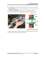
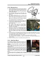
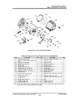
Figure 5-22 Bearing Cover
5.5.10 Bearing Cover
a) Before installing the bearing cover [16], check that the
teeth of the lock washers of the thrust bearing part have
been properly bent to prevent rotation and that the
hexagon head bolts fastening the thrust bearing gland
are with spring washers.
b) For ensuring the safety, screw two stud bolts in the
upper bolt holes on the flange of the low-stage bearing
head [11-1].
c) After applying sufficient amount of oil or like on the
flange surface of the bearing head as well as on both
sides of the bearing cover gasket [17-1], hang the
gasket from the upper stud bolts and attach the gasket
onto the flange surface of the bearing head.
d) While lifting the bearing cover [16] using a lifting hook
on the eye bolt, install the bearing cover carefully not
to make contact with the M rotor shaft
and/or the push rod.
e) After correctly setting the position of the alignment
pins, lightly tap the flange at opposite places
alternately using a copper hammer or soft hammer to
install the cover in position.
f)
When the cover has come to the position the bolts can
be screwed in, screw in two or three hexagon socket
head cap screws [18-1] and evenly tighten them to
reduce the clearance and make the cover contact the
body. Then, tighten all the bolts at the specified
torque.
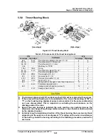
g) There are two types of the hexagon socket head cap screws as [595A] and [595B] shown in Figure
5-22. These bolts are used for fastening the countersunk processed screw holes of the bearing
cover flange surface installing the unloader cylinder.
First, tighten opposite four positions, i. e., up, down, right and left with M24 bolts [595A].
Then, screw two M20 bolts [595B] into thread holes positioned 10:10 of clock, and tighten to the
specified torque.
h) Tighten all remaining bolts [18-1] and [595A] at the specified torque.
5.5.11 Shaft Seal Block
The assembly procedure of the shaft seal block is the
reverse sequence described in Section 5.4.4 as shown in
the order of the colored number of each sectional view
drawing.
Disassembly and assembly works of this block especially
require qualified trained personnel and special tools. For
details contact us.
Note that to confirm the sliding surface pressure of the
mechanical seal is proper or not, measure the clearance
between the surfaces of the seal cover gasket and the
bearing cover flange. This clearance is called " fastening
margin of the seal", it should be measured by using a taper
gauge.
The proper value guide line (reference) of this " fastening
margin of the seal" is; 3 mm as BOD type seal, 5 mm as BBD
Ⅱ
type seal, and 6 mm as BBDE type
seal.

