2201Q4JE-MY-C9-N_2018.01.
Chapter 5 Maintenance and Inspection
Compound 2-stage Screw Compressor
4032**C
5.5 Reassembly
5-52
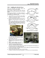
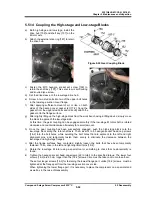
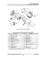
Figure 5-24 Gear Coupling Block
5.5.14 Coupling the High-stage and Low-stage Blocks
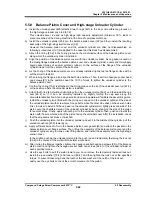
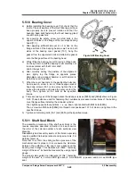
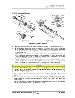
a) Both high-stage and low-stage, install the
drive hub [152] and shaft key [157] on the
M rotor axis.
b) Attach the external snap ring [187] to retain
the drive hub.
c) Fasten the M10 hexagon socket set screw [159] to
retain the shaft key [157]. This set screw is self-locking
and knurled type screw.
d) Set the drive sleeve on the low-stage drive hub.
e) Screw in two stud bolts into two of the upper bolt holes
in the low-stage suction cover flange.
f) After applying sufficient amount of oil, or like. on both
sides of the bearing cover gasket (2) [17-2], hang the
gasket from the upper stud bolts and correctly attach the
gasket onto the flange surface.
g) After slightly lifting up the high-stage block from the work bench using a lifting device, slowly move
the block to approach the low-stage side.
At this time, the gear coupling can be engaged smoothly if the low-stage M rotor shaft is rotated
clockwise and counterclockwise alternately for a small amount.
h) Once the gear coupling has been successfully engaged, push the high-stage block onto the
low-stage block along the rotor shaft axis. Then, insert 4 to 6 hexagon socket head cap screws
[18-2] into the bolt holes, while avoiding the bolt holes that are adjacent to the left and right
alignment pins, and temporarily fasten them evenly to eliminate the clearance between the
low-stage and high-stage flanges.
i) After the flange surfaces have contacted, slightly loosen the bolts that have been temporarily
fastened. Then, drive in the left and right alignment pins [19-2].
j) Rotate the low-stage M rotor using a special tool or something to check that no abnormality is
found.
k) Tighten the hexagon socket head cap screws (22 in total) to the specified torque. The lower four
screws [18-3] are 20 mm longer than the [18-2] screws. Care must be taken not to confuse them.
These four longer screws [18-3] for fastening the lowest flange part, unlike [18-2] screws, must be
tightened at the flange part from the low-stage suction cover side.
When tightening the lower flange part, it is necessary to place the compressor on a special stand
as well as in the case of disassembly.

