background image

2200M4JE-HO-iS2-N_2014.04.  

Chapter 1 Safety 

Screw Compressor i-series 

1.1


Observation/Prevention (DOs and DON'Ts)


1-2


1.1.1.3  DOs on Lockout/Tagout after Shutting Off the Power 

  A lock-out/tag-out mechanism must be installed for the main circuit breakers that supply power 

to the motor and power to the control system. The lock-out/tag-out after power down is a very 

effective means to ensure the safety when two or more workers are working on the system at 

the same time, as it can prevent possible injury of workers that may be caused by accidental 

power-on of the driving source by one of the workers. 


  If there is a risk of danger, especially during cleaning, maintenance/inspection, or 

troubleshooting work, be sure to let the workers perform the lock-out/tag-out procedures after 

the motor main power and control power has been shut off. 


  Because the workers may neglect to perform the lock-out/tag-out procedures or cut-off the 

power in the following situations, be sure to instruct them to strictly follow the correct 

procedure by clearly identifying the work that require lock-out/tag-out and the reasons why it is 

needed. 


As it is a cumbersome task for the workers to cut off the motor main power and control 
power and use lock-out/tag-out devices before starting the work, they might neglect to do 
it. 


The workers might determine by themselves that it should be OK just to cut off the motor 
main power and control power, and not use any lock-out/tag-out devices. 

1.1.1.4  DOs about Personal Protective Gear 

  Prepare and use protective gear complying with the safety standards of the regulations. 

  Check the function of each protective gear before using. 

  Wear designated clothes such as work outfits, with their cuffs tightly closed. 

  Do not wear any neckties or jewelry as there is a risk of being entangled by a movable part or 

rotating part. Put on a helmet as your hair may get entangled. 

  Do not have anything in your pocket to prevent objects from falling into the machine. 

1.1.1.5  DOs about Handling of Hazardous and Toxic Substances 

  Obtain Safety Data Sheet (SDS) from manufacturers of hazardous and toxic substances. 

Check the MSDS and follow the handling instructions recommended by the manufacturers to 

handle and store those substances. 

1.1.1.6  DOs about Handling Emergency Situations 

  Formulate an emergency action plan complying with the regulations, and post it on a safe 

place. 

1.1.1.7  DOs about Waste Oil, Fluid, and Materials 

  Disposing of refrigerant and oil used for this product are subject to a number of regulations for 

the environmental protection purposes. Follow the local, state, federal acts and regulations 

and your company's rules when disposing of such waste oil, fluid and materials. 

1.1.1.8 Other 

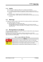
DOs 

  Keep clean the floor around the entire package unit. Provide a safety passage. 

  Walk only on the areas set up as a work floor. Also, do not leave tools and cleaning solutions 

in that area. 

  If water or oil is spilled on this product or the floor, immediately wipe it off to prevent workers 

from slipping and getting injured. 

Summary of Contents for i125L

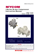
Page 1: ...nual thoroughly to fully understand the contents Keep this instruction manual in a safe designated place for future reference whenever the manual is needed Specifications of this product is subject to change without prior notice This manual is applied to each compressor after the serial number shown below i125S 8750303 i125L 8770301 i160S 8710055 i160M 8720018 i160L 8730030 ...

Page 2: ...esult can use it safely and efficiently Before installing or using this product make sure you read this manual Keep this manual in a safe place near this product for quick reference Revision History Title Document No First edition issue date i Series Screw Compressor Instruction manual 2200M4JE DA iS2 N_2014 04 April 28 2014 Revision No Issue Date Contents of revisions modified clause page and det...

Page 3: ...avy rain flood high tide earthquake subsidence of ground lightning strike fire etc Malfunctions damage or degradation due to misuse or unacceptable use of the product including improperly storing the product outdoors or under too hot humid conditions excessively frequent liquid flow back operation extremely frequent start stop cycles etc Any failure or damage caused by other systems or devices not...

Page 4: ...maintenance and inspection of this product should be performed by qualified personnel educated about the fundamentals of this product and trained about hazards involved and measures to avoid danger Do not allow any person other than those educated on the fundamental expertise of this product and trained about hazards involved and measures to avoid dangers to approach this product while it is opera...

Page 5: ... supplied from outside the refrigeration system or cold storage unit Make sure the power supply on the power source side is shut off and perform lockout tagout to prevent the product from being turned on during work About This Manual This product may be modified without prior notice Therefore the appearance of actual machine may differ from the descriptions in this manual If you have any questions...

Page 6: ...sms Describes the main components of this product functional information specification operating limits drawings and parts list 3 Installation Describes the installation procedure of this product 4 Operation of Compressor and the Package Unit Describes the precautions for operating this product 5 Maintenance Describes sections and period for inspecting and assembly and disassembly of this product ...

Page 7: ...e 1 1 1 1 1 3 DOs on Lockout Tagout after Shutting Off the Power 1 1 1 1 1 4 DOs about Personal Protective Gear 1 2 1 1 1 5 DOs about Handling of Hazardous and Toxic Substances 1 2 1 1 1 6 DOs about Handling Emergency Situations 1 2 1 1 1 7 DOs about Waste Oil Fluid and Materials 1 2 1 1 1 8 Other DOs 1 2 1 1 2 DON Ts 1 2 1 2 Warnings 1 3 1 2 1 Types and Meanings of Warnings 1 3 1 3 Residual Risks...

Page 8: ...acking 3 1 3 2 2 Storage 3 1 3 2 3 Transfer 3 1 3 2 4 Preparation for Installation 3 3 3 2 5 Installation 3 3 3 2 5 1 Piping Connection 3 3 3 2 5 2 Equipment and Devices for Protection of the Compressor 3 3 3 2 6 Airtightness Test 3 4 3 2 7 Lubricant Charge 3 4 3 2 7 1 Initial Charge of Lubricant 3 4 3 2 7 2 Additional Charge of Lubricant 3 5 3 2 8 Charge of Refrigerant 3 5 3 2 9 Check after Insta...

Page 9: ...5 4 3 Refrigerant Gas Treatment 5 8 5 4 3 1 Valves Used 5 8 5 4 3 2 Refrigerant Gas Recovery 5 8 5 4 4 Removing Parts Connected to the Unit 5 9 5 4 5 Removing and Lifting the Compressor 5 10 5 4 6 Removing Oil from Compressor 5 10 5 5 Disassembly and Inspection 5 11 5 5 1 Mechanical seal 5 11 5 5 1 1 Disassembly 5 11 5 5 1 2 Inspection 5 12 5 5 2 Bearing Cover 5 13 5 5 2 1 Disassembly 5 13 5 5 2 2...

Page 10: ... 5 22 5 6 5 2 i160 Series 5 22 5 6 6 Adjustment of Thrust Bearing and End Clearance 5 23 5 6 6 1 End Clearance Measurement 5 25 5 6 6 2 End Clearance Adjustment 5 26 5 6 6 3 Tightening after End Clearance Adjustment 5 27 5 6 7 Balance Piston 5 27 5 6 8 Bearing Cover 5 28 5 6 9 Mechanical seal 5 28 5 6 10 End Cover 5 31 Chapter 6 Troubleshooting Table 6 1 Troubleshooting 6 1 Chapter 7 Related Docum...

Page 11: ... 1 2 DOs on Maintenance Prepare work procedures based on a work plan Be sure to perform danger forecasting before starting the work If two or more people are to work together be sure to mutually check the work details and procedures before the work During the work always keep track of the other workers actions Before working on any troubleshooting during operation before setting up this product be...

Page 12: ...l power and not use any lock out tag out devices 1 1 1 4 DOs about Personal Protective Gear Prepare and use protective gear complying with the safety standards of the regulations Check the function of each protective gear before using Wear designated clothes such as work outfits with their cuffs tightly closed Do not wear any neckties or jewelry as there is a risk of being entangled by a movable p...

Page 13: ... affixed to the compressor itself which this manual is intended for For details about the warning labels affixed to the package unit refer to the instruction manual of the unit 1 2 1 Warning Notices in this Manual The warning messages described in this manual warn dangerous situations that may arise during work by using the following four categories Neglecting such warnings may cause accidents res...

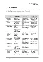
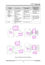
Page 14: ...Detect gas leakage Wear protective gear Work under room temperature D Compressor discharge casing and discharge piping Burn injury due to contact Contact with or inhalation of hazardous substances generated by leakage or spout of refrigerant or the like Keep away and do not touch Wear protective gear Detect gas leakage Wear protective gear Work at a temperature of not higher than 40 C E Solenoid v...

Page 15: ...o contact with driving part Install protective cover on terminals and prohibit opening Keep away and do not touch Wear protective gear Turn off each breaker and the control power and conduct lockout tagout Wear protective gear I Package Unit Oil drain Contact with hazardous substances generated by leakage or spout Burn caused by contact with high temperature fluid Sufficient ventilation Keep away ...

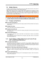
Page 16: ...on control room Stop Restoration Methods For information on how to stop or restore the emergency stop button refer to the instruction manual of the package unit Inspection Method Interval The emergency stop buttons must be tested before commissioning and must also be periodically re tested after that For the inspection method and interval for the emergency stop button refer to the instruction manu...

Page 17: ...manual of the motor Protection from oil level decrease In case of the oil supply by differential pressure install a protection device to the oil separator for protect form oil level decrease Since there is a possibility that alarm for protection from lubricating differential pressure decrease does not activate even if the amount of lubricant is insufficient No Water Alarm If you use water cooling ...

Page 18: ... This compressor employs roller bearings which let lubrication oil reserved in part even when the machine is stopped Accordingly no lubrication failure will occur even with differential pressure oil supply system which has no oil pump installed 3 step 100 75 50 unloader As it has a 3 step 100 75 50 unloader built in flow adjustment can be done easily Inverter controlled speed control is available ...

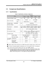
Page 19: ...ries compressors manufactured and shipped in May 2014 or after Capacity control 3 step 100 75 50 unloader Connected pipe size Suction flange MYCOM 100A 4 ANSI 300 5 Discharge flange MYCOM 65A 2 1 2 ANSI 300 3 Oil inlet port Rc1 2 Rc1 Economizer Rc3 8 Rc3 4 Aquamizer Liquid injection Rc1 4 Rc1 2 Unless otherwise noted the pressure unit MPa represents the gauge pressure in this manual For limits of ...

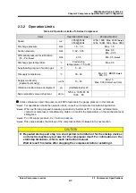
Page 20: ...e Vibration standard value at shipment μm Half amplitude 20 Noise standard value at shipment dB A 125S L 160S M 84 160L 85 Unless otherwise noted the pressure unit MPa represents the gauge pressure in this manual Note 1 For operations outside the operation limits consult our compressor manufacturing division Note 2 When performing a speed increasing operation by inverter at 70 C or above oil tempe...

Page 21: ...s Note 2 MPa High Low 0 6 30 sec 0 5 30 sec Note 3 Discharge temperature C High 90 5 sec 95 0 sec Low Suction temperature C High 60 60 sec Low 58 30 sec 60 30 sec Discharge superheat C High Low 15 60 sec 10 60 sec Suction superheat C High Low 0 30 sec 0 60 sec Lubrication temperature C High 80 60 sec 85 60 sec Low 30 60 sec 25 60 sec Unless otherwise noted the pressure unit MPa represents the gaug...

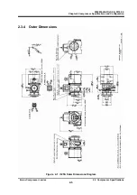
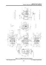
Page 22: ...00M4 JE HO iS2 N_2014 04 Chapter 2 Compressor Specifications and Configuration Screw Compressor i series 2 3 Compressor Specifications 2 5 2 3 4 Outer Dimensions Figure 2 1 i125S Outer Dimensions Diagram ...

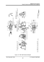
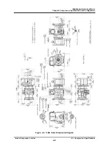
Page 23: ...2200M4 JE HO iS2 N_2014 04 Chapter 2 Compressor Specifications and Configuration Screw Compressor i series 2 3 Compressor Specifications 2 6 Figure 2 2 i125L Outer Dimensions Diagram ...

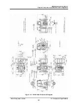
Page 24: ...2200M4 JE HO iS2 N_2014 04 Chapter 2 Compressor Specifications and Configuration Screw Compressor i series 2 3 Compressor Specifications 2 7 Figure 2 3 i160S Outer Dimensions Diagram ...

Page 25: ...2200M4 JE HO iS2 N_2014 04 Chapter 2 Compressor Specifications and Configuration Screw Compressor i series 2 3 Compressor Specifications 2 8 Figure 2 4 i160M Outer Dimensions Diagram ...

Page 26: ...2200M4 JE HO iS2 N_2014 04 Chapter 2 Compressor Specifications and Configuration Screw Compressor i series 2 3 Compressor Specifications 2 9 Figure 2 5 i160L Outer Dimensions Diagram ...

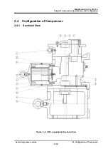
Page 27: ...014 04 Chapter 2 Compressor Specifications and Configuration Screw Compressor i series 2 4 Configuration of Compressor 2 10 2 4 Configuration of Compressor 2 4 1 Sectional View Figure 2 6 i125L Longitudinal Sectional View ...

Page 28: ...2200M4 JE HO iS2 N_2014 04 Chapter 2 Compressor Specifications and Configuration Screw Compressor i series 2 4 Configuration of Compressor 2 11 Figure 2 7 i125L Cross Sectional View ...

Page 29: ...O iS2 N_2014 04 Chapter 2 Compressor Specifications and Configuration Screw Compressor i series 2 4 Configuration of Compressor 2 12 Figure 2 8 i125 Longitudinal Sectional View of Suction Capacity Control Section ...

Page 30: ...2200M4 JE HO iS2 N_2014 04 Chapter 2 Compressor Specifications and Configuration Screw Compressor i series 2 4 Configuration of Compressor 2 13 Figure 2 9 i160S Longitudinal Sectional View ...

Page 31: ...2200M4 JE HO iS2 N_2014 04 Chapter 2 Compressor Specifications and Configuration Screw Compressor i series 2 4 Configuration of Compressor 2 14 Figure 2 10 i160S Cross Sectional View ...

Page 32: ...O iS2 N_2014 04 Chapter 2 Compressor Specifications and Configuration Screw Compressor i series 2 4 Configuration of Compressor 2 15 Figure 2 11 i160 Longitudinal Sectional View of Suction Capacity Control Section ...

Page 33: ...2014 04 Chapter 2 Compressor Specifications and Configuration Screw Compressor i series 2 4 Configuration of Compressor 2 16 2 4 2 Development View of Parts Figure 2 12 Development View of i125S L Parts with Motor Spacer ...

Page 34: ...0M4 JE HO iS2 N_2014 04 Chapter 2 Compressor Specifications and Configuration Screw Compressor i series 2 4 Configuration of Compressor 2 17 Figure 2 13 Development View of i160S L Parts with Motor Spacer ...

Page 35: ...10 3 Hexagon Socket Head Cap Plug NF06 010 R3 8 S45C S 6 L 5 10 4 Hexagon Socket Head Cap Plug NF06 015 R1 2 S45C 1 11 Bearing Head CS01102 I125 i125 1 12 Gasket Bearing Head CS01200 I125 i125 1 16 Bearing Cover CS01602 I125 i125 1 17 Gasket Bearing Cover CS01700 I125 i125 1 18 1 Hexagon Socket Head Cap Screw NB35416 055 M16 55 SCM435 7 20 Spring Pin NE3203 008 Φ3 8 1 22 End Cover CS02202 I125 i12...

Page 36: ...crew NB35406 020 M6 20 SCM435 8 100 Mechanical Seal Assembly CS10002 125EBS BBSE 125 1set 235 1 Motor Spacer CS23502 I125N i125 1 235 2 Plate Motor Spacer CS23510 I125 i125 2 235 3 Hexagon Socket Head Cap Screw NB35406 010 M6 10 SCM435 8 237 1 Torsional Slip Washer M CS23700 F125M FM125 M 1 237 2 Torsional Slip Washer F CS23700 125 125L 1 250 1 Thrust Washer M CS04200 I125M i125M Spacer thrust bea...

Page 37: ...n L type NJ3 0802NE L Φ8 R1 4 JO4050 2 538 Piping QA11 08 Φ8 2 546 Wave Washer ND91 016 FM125 BW16 1 555 Angle Valve NF042 0302N JO5820 R1 4 Rc1 4 2 722 Gland PK CR72200 NR94 VFT 22 9 5T 15 5 9H 1 The part code of the O ring is the one assigned to NBR 70 1 which is standard material When the material of the O ring is other than NBR a different part code is used for each material If you are using O...

Page 38: ...NF06 015 Rc1 2 S45C 15 10 5 Hexagon Socket Head Cap Plug NF06 020 Rc3 4 S45C 1 10 6 Hexagon Socket Head Cap Plug NF06 025 Rc1 S25C 2 11 Bearing Head CS01102 I160 i160 1 12 Gasket Bearing Head CS01200 I160 i160 t 0 5 1 16 Bearing Cover CS01602 I160 i160 1 17 Gasket Bearing Cover CS01700 I160 i160 t 0 5 1 18 1 Hexagon Socket Head Cap Screw NB35412 040 M12 40 SCM435 40 20 Spring Pin NE3203 010 3 10L ...

Page 39: ... Oil Seal CS04800 160 160 1 49 O ring PA12 090 JIS B 2401 G90 1 50 Oil Seal Rareflon CS05000 160VD 160 S55 70 9 1 51 Seal cover CS05102 160 160 1 52 Gasket Seal Cover CS05200 160N 160 t 0 5 1 58 Hexagon Socket Head Cap Screw NB35408 030 M8 30 SCM435 8 70 Discharge Port Cover CS07000 I160 i160 1 93 Gasket Suction Flange PL300 125 ANSI 300 5 1 96 Gasket Discharge Flange PL300 080 ANSI 300 3 1 100 Me...

Page 40: ...sure NN410 080 Rc3 8 80L Sch40 2 535 Connection L type NJ3 0803NE L Φ8 R3 8 JO4060 2 536 Connection L type NJ3 0802NE L Φ8 R1 4 JO4050 2 538 Piping QA11 08 Φ8 2 550 Check Union KD122 12E I Φ12 R3 8 L 2 S M 1 551 Connection I type NJ2 1203NE I Φ12 R3 8 JO4570 L 2 S M 1 552 Piping QA11 12 Φ12 1 553 Connection I type NJ2 1002NE I Φ10 R1 4 1 554 Angle Valve NF067 02 TC 1 R1 4 Rc1 4 1 555 Angle Valve N...

Page 41: ...rotruding tooth profiles is called a male or M rotor and the rotor having 6 concave profiles is called a female or F rotor In this manual they are referred to as M rotor and F rotor The compressor is driven by the motor connected to the shaft of the M rotor Figure 2 14 Compressor Mechanism 2 5 2 Suction Process As shown in Figure 2 15 the rotors with different tooth profiles are engaged As the rot...

Page 42: ... H The volume ratio represented by each symbol screw compressor is as follows L 2 63 M 3 65 H 5 80 Volume of suctioned refrigerant gas immediately before the start of compression Vi Volume of refrigerant gas just before pushed out to discharge port Decide which volume ratio L M or H should be used according to operating conditions If the compressor is used with a volume ratio that does not match o...

Page 43: ... Vi to load condition Both the required compression ratio and Vi are low Both the required compression ratio and Vi are high B Improperly adapted Vi to load condition Too low Vi compared with necessary compression ratio Too high Vi compared with necessary compression ratio Figure 2 19 Relationship between Volume ratio Vi and Operation Conditions ...

Page 44: ... be performed only by electrical engineers 3 2 Installation Works 3 2 1 Unpacking Check that there are no abnormalities such as damage on the compressor If there are abnormalities or deficient parts on the compressor please contact one of our local sales offices or service centers immediately Unnecessary packing materials should be discarded according to the laws and ordinances or your company s r...

Page 45: ...Then reel up the wire ropes a little further until the compressor is slightly up away from the ground Check that the compressor is not tilted If the compressor is tilted return the compressor to the ground and correct the tilt by adjusting the wire ropes After that restart the lifting operation 11 Be sure to lift up the compressor slowly If it is lifted rapidly it may damage the lifting tools such...

Page 46: ... with nitrogen gas to prevent rust Be sure to release the pressure before starting piping work Be sure not to allow moisture to enter the piping There is a high probability that it will cause trouble after the start of operation Be sure to assemble piping when it is dry Improper piping may cause operating problems such as oil not returning to the compressor or liquid flow backs When connecting the...

Page 47: ... Keep that pressure for at least 30 minutes and perform a leak test on the connecting jointing parts like flanges by using leakage detection liquid soapy water etc 3 2 7 Lubricant Charge In the packaging of the refrigerating unit install two valves at the front and the rear of an oil filter Install an oil charge port between the oil filter and the upstream side valve When refilling lubricant ensur...

Page 48: ...bricant refer to the instruction manual of the package unit 3 2 7 2 Additional Charge of Lubricant For additional charge of lubricant during operation follow the procedure described in the instruction manual of each package unit The applicable procedure differs among units and operating conditions 3 2 8 Charge of Refrigerant Charge refrigerant referring to the refrigerating cold storage package un...

Page 49: ...hould be the viscosity the oil shows at the oil inlet of the compressor The viscosity of lubrication oil significantly changes depending on the type of the refrigerant used in combination with the oil If the refrigerant dissolves in the oil or the oil and refrigerant are inter soluble the viscosity of the oil drops to a level remarkably below the level required for operation of the compressor unde...

Page 50: ... Exxon Mobil GARGOYLE ARCTIC 300 68 Exxon Mobil CAPELLA WF46 46 Texaco CAPELLA WF68 64 Texaco CP 1009 32 34 CPI Hydrotreated paraffinic base CP 1009 68 69 CPI REFLO 46A 46 Petro Canada REFLO 68A 58 Petro Canada CAPELLA PREMIUM 67 Texaco RHT 68 68 Kluber REFLO XL 59 Petro Canada Synthetic Oils non inter soluble oils Brand Kinematic viscosity 40 C mm2 s Manufacturer Type Acemire 300 59 Acemire AB My...

Page 51: ...ands of lubricant are used the different additives in the lubricant may react with each other and produce foreign substances like slurry If it is necessary to change the brand of lubricant collect as much as oil as possible from the compressor as well as from the condenser evaporator and all other refrigerating unit components before charging the new lubricant After 100 to 200 hours of operation r...

Page 52: ...to flow to the unit s condenser for at least 15 minutes Check the condensing pressure by using the pressure gauge of the compressor 2 Check the cooling water temperature 3 Compare the condensing pressure checked in step 1 above with the refrigerant saturation pressure that depends on the cooling water temperature as shown in Table 4 1 4 When the pressure inside the condenser and the refrigerant sa...

Page 53: ... compressor is stopped for more than a month conduct the following once a month Measure the unit pressure Check for refrigerant leakage Do the procedure described in this manual Chapter 3 section 3 2 7 1 When restarting the compressor which has been stopped for more than a year check for the leakage of refrigerant and replace the oil Also measure the insulation resistance of the motor Supply power...

Page 54: ...Do not modify the compressor or any of its parts without MAYEKAWA s permission It may cause the compressor to be damaged or disabled from maintaining its normal functions When disassembling the compressor remove it from the unit frame and place it on a work bench Before removing the compressor from the unit frame recover the refrigerant from the unit properly and check that the pressure inside the...

Page 55: ...ent of periodic maintenance interval Suction pressure Mpa Difference from the set value of evaporation temperature equivalent pressure Contamination on the cooling pipe surface Temperature flow rate etc of the object to be cooled Discharge pressure MPa Difference from cooling water temperature equivalent condensing pressure Contamination on condenser cooling pipes Non condensable gases mixed into ...

Page 56: ...ting hours exceeds 500 hours check the suction strainer If a temporary filter is installed for the initial stage of operation remove it At the beginning of the operation or after periodical check the pressure difference between the front and back of the suction strainer may increase quickly If the differential pressure becomes large check and clean the suction strainer 4 Lubricant leak rate from m...

Page 57: ... the pressure difference between the front and back of the suction strainer increases check and clean the suction strainer Check and clean once per year Lubricant Replace after 500 hours from the initial operation Analyze oil every 6 months When the analysis results do not meet the management criteria provided in 5 3 Management of Lubricant of this manual replace oil Oil filter Replace lubricant o...

Page 58: ...n Application example Recommended Overhaul Interval Relatively stable operating condition Refrigeration and cold storage Every 5 years or 40 000 operating hours Relatively changing operating condition Ice maker chiller Every 4 years or 30 000 operating hours Frequently started stopped and relatively changing operating condition Heat pump Every 3 years or 20 000 operating hours Note 1 The above gui...

Page 59: ...ion level Max 15 mg 100 mL as measured by gravimetric Millipore filter method See Note 2 Note 1 Synthetic oils inter soluble with ammonia are so highly hygroscopic that they can absorb moisture at the time of sampling In addition the ammonia content they have absorbed may be detected as the water content at the time of the analysis making it difficult to precisely measure the water content Therefo...

Page 60: ...er who enters the equipment should perform lockout tagout The worker who performed lockout tagout should release them after checking that all work procedures have completed If refrigerant gas or a mixture of refrigerant and oil remains in the compressor refrigerant gas may blow off when the closed circuit is opened This may result in injury such as frostbite or loss of vision Be sure to confirm th...

Page 61: ...0 1 12 Gasket Bearing Head CS01200 I125 i125 1 17 Gasket Bearing Cover CS01700 I125 i125 1 23 Gasket End Cover CS02300 I125 i125 t 1 0 1 27 1 Radial Bearing CS02800 FM125M FM125M 2 27 2 Radial Bearing CS02800 FM125F FM125F 2 30 Balance Piston see Note 2 CS03000 I125 i125 1 33 Sleeve Balance Piston see Note 2 CS03300 I125 i125 1 35 O ring see Note 1 PA11 016 JIS B 2401 P16 1 38 1 Thrust Bearing M C...

Page 62: ... 1 100 Mechanical Seal Assembly see Note 3 CS10002 160EBS 160V BBSE 1set 150 1 O ring see Note 1 PA12 110 JIS B 2401 G110 1 150 2 O ring see Note 1 PA12 115 JIS B 2401 G115 1 216 2 Flange Gasket Oil Inlet Port CR72000 025N MYCOM 25A 1 237 1 Torsional Slip Washer M CS23700 FM160M FM160 1 237 2 Torsional Slip Washer F CS23700 160 160 1 395 Gasket Unloader Cover CS39500 I160 i160 t 1 0 2 480 Strainer...

Page 63: ...ow pressure side If there is another refrigerating unit connected by bypass piping or which can be temporarily installed operate the other compressor and lower the pressure Operate the refrigerating unit close the refrigerant fluid supply master valve and collect the liquefied gas in the receiver By using a refrigerant recovery machine recover the liquefied refrigerant in the receiver For any of t...

Page 64: ...for capacity control solenoid valves 6 Motor spacer 7 Bolts for installing compressor leg bolts Since remaining oil may leak out when disconnecting the oil piping from the compressor slightly loosen the piping and observe the oil flow to decide whether to disconnect the piping right now or extract oil first from the oil temperature gauge on the lubrication header When disconnecting electrical wiri...

Page 65: ...ight hexagon socket head cap screws securing the seal cover 51 remove six and leave the two on the opposing sides b Loosen the remaining two screws alternately and evenly a little at a time After a certain amount of loosening the seal cover of the mechanical seal will be pushed by the repulsion force of the bellows and a gap will appear A gap will not appear if the gasket is stuck In that case rem...

Page 66: ...se leaks i Screw two eye bolts removal tools into the forcing screw holes Then pull out the seal retainer while maintaining a right angle to the rotor shaft j Remove the mating ring from the seal cover At this time be careful not to damage the mating ring 5 5 1 2 Inspection a Mechanical seal should be replaced if any defect is found during inspection Actually however it is sometimes difficult to f...

Page 67: ...nt pins 3 by using a tool slide hammer Photo 006 b Attach lifting tools and remove all of the hexagon socket head cap screws If the bearing cover gasket 17 is stuck use a jack bolt to remove At this moment lubricant remaining inside the bearing cover will flow out Prepare a container to catch oil c Remove the bearing cover 16 Exercise care not to let it hit against the shaft and cause damage 5 5 2...

Page 68: ...re the large and small outer diameters of the balance piston at four locations each If either of the maximum values indicates that the part is worn down to or beyond the replacement criteria shown in Table 5 9 the part should be replaced with a new one When replacing with new ones replace the balance piston and balance piston sleeve in a set Table 5 9 Balance Piston Replacement Criteria 5 5 4 End ...

Page 69: ...of lock washers 40 1 40 2 c Loosen lock nuts 39 1 39 2 by using a dedicated lock nut socket If at this moment the rotor shaft rotates attach dedicated rotation stoppers 1 and 2 refer to sectioon 7 2 in this manual during work d Remove lock nuts torsional slip washers 237 1 237 2 and thrust washers 250 1 250 2 e Take out thrust bearings 38 1 38 2 Since the inner race of the bearing is slide fit on ...

Page 70: ... may lead to deterioration in performance or damage to the compressor 5 5 7 1 Disassembly a When using the i125 series remove snap ring 29 3 from the F rotor b As it is heavy in weight be careful when handling As the i160 series rotor weighs more than 30 kg use lifting tools such as chain blocks and nylon belts Pull out about two thirds of the rotor attach a belt around its outer circumference and...

Page 71: ... found defective However if there is an extreme problem find the cause and review the operating state or periodic inspection interval to prevent recurrence of such problem 5 5 9 Suction Strainer and Check Valve The structure of the suction strainer and check valve differ between i125 and i160 5 5 9 1a Disassembly i125 a Remove strainer cover 5 2 Remove wave washer 546 strainer element 480 and O ri...

Page 72: ...ner cylinder of the strainer element may be deformed but this is normal c The gasket O ring and valve seat must be replaced with new ones 5 5 10 Unloader 5 5 10 1 Disassembly a Attach lifting tools to the motor side end face of the main rotor casing and lay down the unloader horizontally b Remove Φ8 piping 538 c Of the bolts securing unloader cover 393 remove all but the two on the opposing sides ...

Page 73: ...ct standard size material use for fixed portion or sliding portion etc Incorrect replacement can lead to defects such as oil leakage Some gaskets are asymmetrical In that case ensure that the assembly direction is correct If the assembly direction is not correct problems such as blocking of oil passages machined in the casing may occur resulting in serious defects Start assembly after disassembly ...

Page 74: ... sufficiently adjusted By using fine emery paper remove over any damage on the shaft surface of the bearing and seal Both the M and F rotors have a certain engagement positions which are indicated by stamp marks Photo 018 M Rotor Mating Mark Photo 019 F Rotor Mating Marks a Shrink fit the inner ring of radial bearings 27 1 27 2 to both the M and F rotors The inner ring may move upward as it cools ...

Page 75: ...r casing and apply sufficient oil Photo 022 b While lifting bearing head 11 with lifting tools temporarily tighten it with the 4 bolts c After driving the alignment pin in position tighten the bolts and remove the lifting tools Photo 022 Affixing Gasket Photo 023 Installing Bearing Head 5 6 4 Outer Ring of Radial Bearing a Attach the outer ring of the radial bearing to the main rotor casing and be...

Page 76: ...properly d Assemble O ring 7 strainer element 480 and wave washer 546 Install strainer cover gasket 6 2 and the strainer cover 5 2 5 6 5 2 i 160 Series a Install O ring 495 valve plate 490 valve seat 489 seat stopper 488 and plain washer 487 to check valve shaft 491 Tighten hexagon nut 486 b Insert the check valve shaft to the side of main rotor casing Install strainer cover gasket 6 and check val...

Page 77: ... Lock Nut 1 1 39 2 Lock Nut 1 1 40 1 Lock Washer 1 1 40 2 Lock Washer 1 1 41 1 Spacer Thrust Bearing Outer Race M 1 1 41 2 Spacer Thrust Bearing Outer Race F 1 1 42 1 Spacer Thrust Bearing Alignment M 1 1 42 2 Spacer Thrust Bearing Alignment F 1 1 43 1 Thrust Bearing Gland M 1 1 43 2 Thrust Bearing Gland F 1 1 45 Hexagon Head Bolt 8 8 46 Spring Washer 8 46 1 Spring Washer 8 46 2 Plain Washer 8 237...

Page 78: ...d mark on the machine s inner side by using blue sharpening stone b After assembling the thrust bearing install thrust washers 41 1 41 2 lock washers 40 1 40 2 and torsional slip washers 237 1 237 2 c Attach dedicated shaft rotation stoppers 1 and 2 Tighten lock nuts 39 1 39 2 to the specified torque shown in Table 5 13 or to the specified tightening angle shown in Table 5 14 see 7 1 Tightening An...

Page 79: ...ust bearing inner ring is secured to the rotor shaft by using a tool such as the handle edge of a soft hammer Alternatively by using a chamfered part of the lock nut pull out the rotor with the edge of a flat blade screwdriver b When the rotor has been pushed to the discharge side prepare to install the thrust bearing gland Attach a dial gauge to the edge of the shaft and match the needle to 0 Pho...

Page 80: ...ified value or ask professional vendors to do so After grinding the flat surface measure the whole circumference of the spacer by using a micrometer and check that the thickness is even Rotor axial runout measurement When the end clearance has been adjusted to within the specified range place a dial gauge on the seal attachment portion of the M rotor shaft FIgure 5 4 Measure axial runout by turnin...

Page 81: ...cally to the flange surface of the main rotor casing Apply sufficient oil to the flange surface Photo 031 and then place bearing cover gasket 17 Photo 032 Take note that the gasket has right left difference b While using lifting tools temporarily tighten bearing cover 16 with 4 bolts c After driving the alignment pin in position Photo 033 tighten the bolts and remove the lifting tools Photo 031 Ap...

Page 82: ...e tapping sound and feel After assembly check that the step formed at the boundary between the oil seal and the retainer is even See from the opposite side and confirm that they are evenly assembled d Use two eye bolts M8 to assemble the seal retainer with the oil seal along the rotor shaft At this time ensure that the retainer s oil hole is on the upper side of the rotor shaft and accurately alig...

Page 83: ...tall the seal cover with the gasket so that the oil removal piping of the seal cover is on the bottom side At this time assemble it carefully either at a right angle or by delaying the upper side slightly while paying attention not to cause the mating ring inside the seal cover hit against the rotor shaft The seal collar and the mating ring sliding surface will come into contact midway through att...

Page 84: ... tightening the seal cover evenly at positions 180 degrees apart When the gasket surface gets free of gap tighten all of the remaining screws m When tightening of the seal cover is finished supply oil to the seal cover while rotating the shaft n After supplying oil be sure to install the plug Photo 041 Supplying Oil 5 6 10 End Cover a Screw two stud bolts i125 M12 i160 M16 symmetrically and then p...

Page 85: ... clogging Failure of magnet relay etc in compressor startup circuit Aging degradation Replace with a new one Poor installation environment Replace ventilation fans etc if defective Improve temperature humidity and ventilation at the installation site 02 Compressor stops immediately after startup Low pressure protection circuit activates Insufficient refrigerant flow Insufficient refrigerant Insuff...

Page 86: ...vely when the machine is stopped and oil loss occurs at startup Inspect oil heater alone inspect relays etc on related circuits and replace parts as necessary Insufficient oil return due to insufficient refrigerant circulation Correct insufficient refrigerant circulation and return oil from load side heat exchanger Supply lubricant temporarily Troubles such as clogging in oil return passage Remove...

Page 87: ...of insufficient flow of cooling water etc Inspect filters installed on the circulation route for clogging and contamination and take necessary actions Inspect for leaks in circulation routes and take necessary actions Inspect water supply routes mechanisms and take necessary actions If frozen take measures such as improvement of heat insulation or increase of temperature Deficiency in heat exchang...

Page 88: ... Open the valve or perform emergent stop Be sure to conduct tagout while handling valves Be sure to check valves before starting the compressor 06 Discharge temperature is abnormally high Overheated during operation Insufficient refrigerant flow See the causes listed in item 02 above Heat load on load side is higher than design value Inspect the conditions on load side warehousing volume opening c...

Page 89: ... less than the level set by the equipment s design conditions review the operating conditions and set control such that equipment is started stopped less frequently In case of capacity control malfunction see Capacity control malfunction in item 09 The amount of lubricant contained in refrigerant gets smaller resulting in decreased viscosity In case of liquid flow back remove the cause s If oil he...

Page 90: ...her As the sliding surfaces are very hard and dense they need time to fit together Squeaking itself does not cause leak from seal or deterioration in sealing function Normally squeaking is heard for several dozens of hours however it may last longer in rare cases In this case contact one of our service centers 09 Capacity control malfunction Failure of capacity control solenoid valve or related re...

Page 91: ...back during operation Notable frosting on the suction side In many cases flow back of mist steam rather than liquid occurs Sometimes gas liquid separator accumulator is attached to prevent this symptom See also the causes in item 02 Insufficient refrigerant flow Aperture of liquid supply expansion valve is large In case of temperature type expansion valve check the condition of temperature sensiti...

Page 92: ...h as piled up load improve the conditions Ensure the flow of heating medium through the heat exchanger on the load side Heat exchange failure in heat exchanger on load side Heat exchanger conditions Check for any blocked heat transmission tubes or fan failure If any problem is found take necessary actions Foreign substances entering the compressor Welding spatter etc flowing from upstream side Che...

Page 93: ... stopper not set to thrust bearing gland spring washer not assembled etc Tighten lock nuts to the specified torque or torque angle see 7 1 Tightening Angles for Lock Nuts in this manual Be sure to record data on the assembly check sheet to prevent omission of work steps Resonance vibration This occurs when the frequency of vibration comes close to the natural frequency of any component in the enti...

Page 94: ...lock nut at the right side edge of the rotor groove where the stopper tongue of the lock washer fits in as shown in Figure 7 1 c From this marking position tighten the lock nut in such a way that rotation can be stopped within the tightening angle range shown in Table 7 1 i125 i160 30 40 first time tightening 20 30 second time tightening for both 39 1 and 39 2 When measuring the angle use an angle...

Page 95: ...g ring pliers Snap ring pliers external 205 mm tip size Φ2 3 mm internal 300 mm tip size Φ3 0 mm Lock nut socket Nut dimensions AN 8 AN 11 AN 9 AN 12 Eye Bolt M8 two piece set Hexagon socket width across flat 8 mm 10 mm 14 mm 5 mm 8 mm 10 mm 14 mm Socket for socket wrench 13 mm Socket adapter 19 5 female 12 7 male Socket wrench handle 12 7 male L 300 mm Extension bar 12 7 male L 250 or 300 mm Pres...

Page 96: ...re oil supply system Therefore it is necessary to secure the lowest oil supply pressure high and low differential pressure to prevent damage by the poor lubrication of bearings and the mechanical seal assembly Install the oil filter s less than 15 μm β12 75 filtration precision in the oil line to the compressor to prevent the entry of foreign matter such as dust The gas suction side inside of the ...

Page 97: ...oled type Figure app 2 Figure app 3 is the reference flow of the thermo siphon oil cooler Shell and tube type or plate type are general Even in the oil cooler of either method install the oil cooler of adequate capacity to cover the oil radiation amount of the compressor Also design considering a piping pressure loss and a refrigerant liquid water head Figure app 3 Figure app 4 is the oil cooling ...

Page 98: ... valve is general Figure app 5 Economizer i series compressor has a economizer port for improvement of refrigerating effect Figure app 6 is a use example of the general economizer system with the i series compressor package unit DX type composed by a expansion valve and a heat exchanger and flash tank type inhaling from common flash tank are general Install a filter with the ability for filtration...

Page 99: ...fficient 3 Sufficient stiffness If a horizontal type of oil separator with the compressor and motor mounted on top is adopted the oil separator must be sufficiently rigidly designed Figure app 7 is an example flow with oil separator Choose an appropriate oil separation method coalescer demister cyclone system according to the condition of your refrigeration system Figure app 7 Protection Devices P...

Page 100: ...803 TEL 011 631 2052 FAX 011 631 2053 Tohoku Branch 8 72 ROKUTYONO MEMINAMI MACHI WAKABAYASHI KU SENDAI CITY MIYAGI 984 0013 TEL 022 288 5001 FAX 022 288 5155 Kanto Branch 3 14 15 BOTAN KOTO KU TOKYO 135 8482 TEL 03 3642 8968 FAX 03 3641 8468 Chubu Branch 2 9 6 MARUNOUCHI NAKA KU NAGOYA CITY AICHI 460 0002 TEL 052 218 3307 FAX 052 218 3308 Kansai Branch 1 4 27 EBIE FUKUSHIMA KU OSAKA CITY OSAKA 55...

Page 101: ...SEATTLE OFFICE 2615 W CASINO ROAD UNIT 3D EVERETT WA 98204 U S A TEL 1 425 645 9400 FAX 1 425 353 3344 MAYEKAWA U S A INC PORTLAND OFFICE 4700 SW MACADAM AVENUE SUITE 201 PORTLAND OREGON 97239 U S A TEL 1 971 230 1795 FAX 1 503 224 9259 MAYEKAWA U S A INC COVINA OFFICE 1272 CENTER COURT DR SUITE 106 COVINA CA 91724 U S A TEL 1 626 598 5030 FAX 1 MAYEKAWA U S A INC SAN ANTONIO OFFICE 1219 SAFARI SA...

Page 102: ... ISTANBUL TURKEY TEL 90 212 4653631 FAX 90 212 4653635 N V MAYEKAWA EUROPE S A BULGARIA 24 KAMEN ANDREEV STR 1303 SOFIA BULGARIA TEL 359 2 8910130 FAX 359 2 8910131 MAYEKAWA ITALIA S R L MILANO OFFICE VIA RICCARDO LOMBARDI 19 12 20153 MILANO ITALY TEL 39 02 4892 9159 FAX 39 02 453 1728 MAYEKAWA ITALIA S R L BOLOGNA OFFICE VIA PRADAZZO 7 40012 CALDERARA DI RENO BOLOGNA ITALY TEL 39 051 726 364 FAX ...

Page 103: ... TOWER 13 MERALCO AVENUE SAN ANTONIO ORTIGAS CENTER PASIG CITY 1605 PHILIPPINES TEL 63 2 706 0473 FAX 63 2 706 0475 MAYEKAWA PHILIPPINES CORP GENARAL SANTOS OFFICE ROOM 4 LEAH DAPROZA BUILDING FISCAL DAPROZA AVENUE GENERAL SANTOS CITY 9500 PHILIPPINES TEL 63 83 552 3282 FAX 63 83 301 2698 MAYEKAWA SINGAPORE PTE LTD 6 TAGORE LANE SINGAPORE 787470 TEL 65 6451 1565 FAX 65 6451 4932 MAYEKAWA TAIWAN CO...

Page 104: ... TOWER BLDG TOWER A BANGNA TRAD RD K M 6 5 BANGKAEW BANGPLEE SAMUTPRAKARN 10540 THAILAND TEL 66 2 751 9610 FAX 66 2 751 9565 MAYEKAWA THAILAND CO LTD TRANG BRANCH 1 7 TRANG PALIAN RD MUANG TRANG 92000 THALAND TEL 66 75 224 784 FAX 66 75 224 351 MAYEKAWA VIETNAM ONE MEMBER CO LTD ROOM 305 3FL TUOI TRE TOWER 60A HOANG VAN THU WARD 9 PHU NHUAN DIST HO CHI MINH CITY VIETNAM TEL 84 8 3997 5284 FAX 84 8...

Page 105: ...ILE TEL 56 65 257570 FAX 56 65 288073 MAYEKAWA ECUADOR S A CALLE 15B Y AV GUILLERMO PAREJA C C STEFANY LOCAL 4 CALLA LA GARZOTA 1 MZ 28 SOLOR 13 GUAYAQUIL ECUADOR TEL 593 4 262 9108 FAX MAYEKAWA COLOMBIA S A S TRANSVERSAL 93 NO 53 48 INTERIOR 37 PAQUE INDUSTRIAL EL DORADO BOGOTA COLOMBIA TEL 57 1 430 9980 FAX 57 1 437 0988 MAYEKAWA COLOMBIA S A S MEDELLIN OFFICE DIRECCION CR 43B No 8 SUR 10 OFICIN...

Page 106: ...860 FAX MAYEKAWA DO BRASIL EQIPAMENTOS INDUSTRIAIS LTDA LINHARES BRANCH AV GOVERNADOR CARLOS LINDENBERG 873 107 CENTRO CEP 29900 020 LINHARES ES BRASIL MAYEKAWA DO BRASIL EQIPAMENTOS INDUSTRIAIS LTDA MACAE RUA PROFESSOR MARIETA PEIXOTO 62 CENTRO MACAE RJ CEP 27910 250 BRASIL TEL 55 22 2772 6069 FAX 55 22 2759 3112 MAYEKAWA DO BRASIL EQIPAMENTOS INDUSTRIAIS LTDA RIO DE JANEIRO BRANCH AV LUIZ CARLOS...

Page 107: ...ENITO JUAREZ C P 03100 MEXICO D F MEXICO TEL 52 55 5062 0870 FAX 52 55 5062 0898 MAYEKAWA DE MEXICO S A DE C V GUADALAJARA OFFICE SANTA MARIA No 3086 COL VALLARTA SAN LUCAS GUADALAJARA JALISCO C P 44690 MEXICO TEL 52 3336 15 5765 FAX 52 3336 15 1307 MAYEKAWA DE MEXICO S A DE C V MONTERREY OFFICE AV CHAPULTEPEC NO 2233 OTE FRACC BUENOS AIRES MONTERREY N L C P 64800 MEXICO TEL 52 81 8347 3085 FAX 52...

Page 108: ...2200M4JE HO iS2 N_2014 04 MAYEKAWA MFG CO LTD 3 14 15 Botan Koto ku Tokyo 135 8482 Japan TEL 03 3642 8181 URL http www mayekawa com ...

Reviews: