background image

No.QT33-04003A  


11


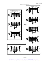
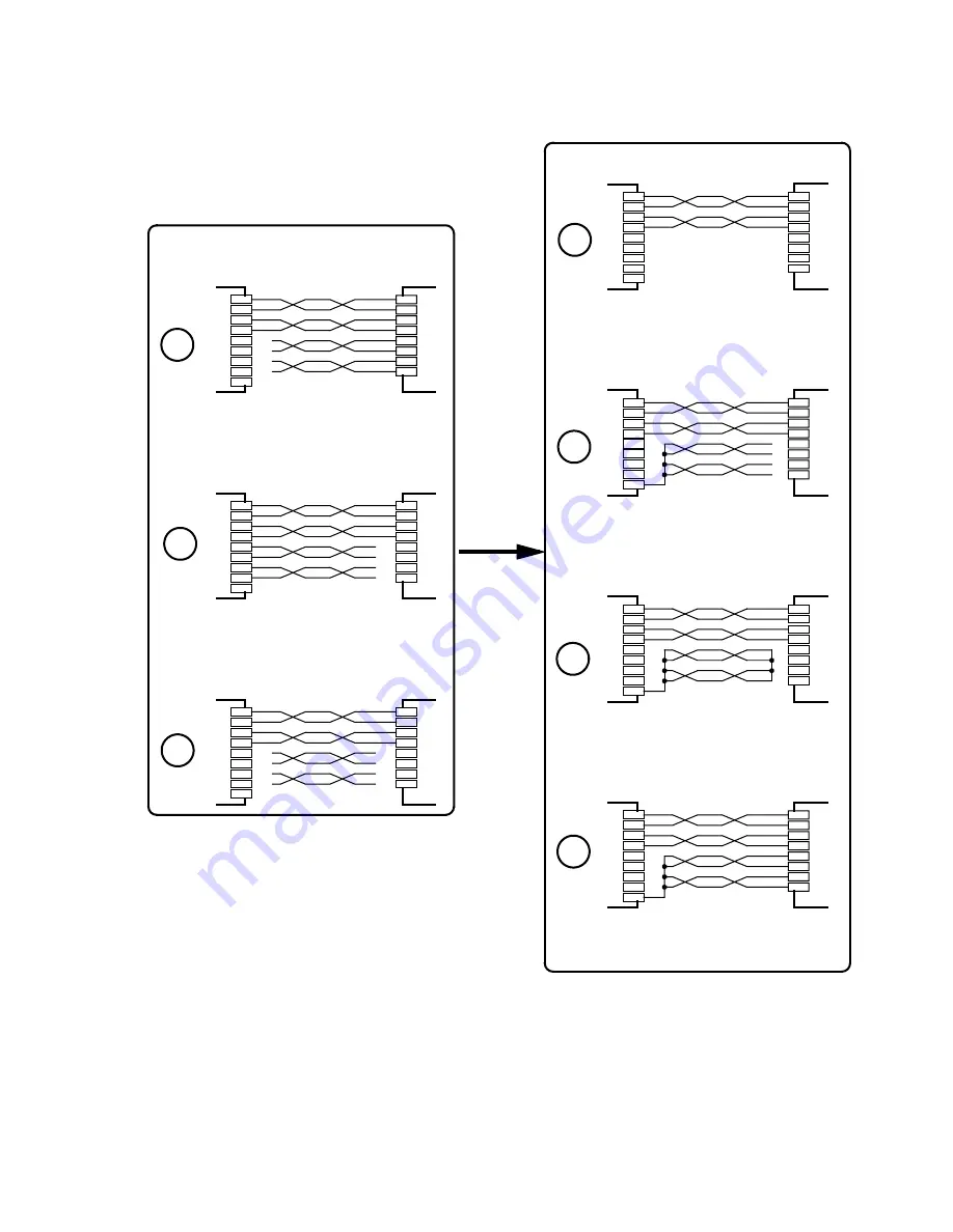
Twisted pair wiring diagram 

Recommended w ir ing

Upp

er

(Co

nt

ro

ller

)

Upp

er

(Co

nt

ro

lle

r)

Upp

er

(Co

nt

ro

ller

)

Upp

er

(Co

nt

ro

lle

r)

Upp

er(

Con

tro

lle

r)

Upp

er

(Co

nt

ro

lle

r)

Upp

er(

Con

tro

lle

r)

W ir ing wh ich has  the poss ib l ity 

GND

GND

GND

GND

GND

GND

GND

of incorrect operat ion

INS

20

INS

20

INS

20

INS20

INS20

INS20

INS

20


・  ①

 of shield line wiring diagram is recommended in case of shield line but select and use a suitable 

diagram of 

 to 

  depending on cable and environment. However do not wire as 

A   to  

C  

Artisan Technology Group - Quality Instrumentation ... Guaranteed | (888) 88-SOURCE | www.artisantg.com

Summary of Contents for NanoDrive INS20 Series

Page 1: ...service in house repair center WE BUY USED EQUIPMENT Sell your excess underutilized and idle used equipment We also offer credit for buy backs and trade ins www artisantg com WeBuyEquipment REMOTE IN...

Page 2: ...No QT33 04003A 2 phase stepping motor Driver NanoDrive INS20 series User s manual Artisan Technology Group Quality Instrumentation Guaranteed 888 88 SOURCE www artisantg com...

Page 3: ...134 USA TEL 1 408 232 7700 Home Page http www nyden com MYCOM TECHNOLOGY INC 2Fl No 333 Fuhsing N Road Taipei Taiwan R O C TEL 886 2 2719 0525 MYCOM KOREA INC Rm 301 Keum Chang Bldg 328 1 6Ka Dangsan...

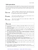
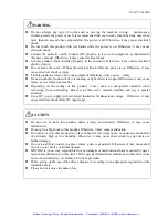
Page 4: ...s near a flammable material Otherwise it may cause fire or electrical shock Leave works such as installation wiring operation checking and maintenance to experts who have enough knowledge on this prod...

Page 5: ...w an unexpected operation when recovering from overheating Please read this user s manual carefully and pay a special attention Use a DC power supply with reinforced insulation for dangerous voltage O...

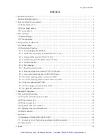
Page 6: ...h 1P 2P SW 9th pole 8 4 2 9 Auto current down function A CD SW10th pole 8 4 2 10 Current adjusting volume of current C ADJ 8 4 2 11 Current adjusting volume of current down CC ADJ 8 4 2 12 Motor conne...

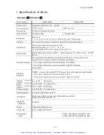
Page 7: ...y Power input Motor leads collection terminal PE terminal Power input Motor leads collection terminal Signal I O terminal Dielectric Strength 2 0kV 60Hz Insulation Resistance 100M or more with applied...

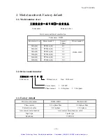
Page 8: ...B 2 0 268A B PF268 A B 2 0 INS20 210 2 2 Driver model number 2 3 Factory default Driver model number INS20 010 INS20 210 Phase current 0 8 A phase Max 2 0 A phase Max Current down value 0 4 A phase 1...

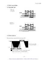
Page 9: ...of the below shown waveform M OT OR C W CC W Pu lse C W C C W C W CC W M OT OR C C W C W T3 0 2 sec or shorter T1 T2 0 2 sec or longer T2 Motor starts to rotate by r is ing edge of wavefor m th is sec...

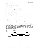
Page 10: ...of Auto current down function A CD 10th pole This turns on off the auto current down function Current adjust volume for current C ADJ This adjusts the current when motor run Current adjust volume for...

Page 11: ...ture of internal heat sink exceeds about 70 Then a signal is outputted to the HEAT output of CN Please refer 5 Example of wiring 4 2 5 Overheat function When a HEAT output is outputted driver receives...

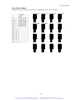
Page 12: ...8 O N 1 0 9 4 3 2 1 5 6 7 8 O N 1 0 9 4 3 2 1 5 6 7 8 O N 1 0 9 4 3 2 1 5 6 7 8 O N 1 0 9 4 3 2 1 5 6 7 8 O N 1 0 9 4 3 2 1 5 6 7 8 O N 1 0 9 4 3 2 1 5 6 7 8 O N 1 0 9 4 3 2 1 5 6 7 8 O N 1 0 9 4 3 2...

Page 13: ...w up control resolution The resolution which carries out an angle change per one pulse O N 1 0 9 4 3 2 1 5 6 7 8 O N 1 0 9 4 3 2 1 5 6 7 8 O N 10 9 4 3 2 1 5 6 7 8 O N 10 9 4 3 2 1 5 6 7 8 O N 1 0 9 4...

Page 14: ...ul of heat generation of a motor and a driver 4 2 10 Current adjusting volume of current C ADJ Motor run current adjust 4 1 Each part name 4 2 11 Current adjusting volume of current down CC ADJ During...

Page 15: ...Use AWG18 0 75mm2 or bigger wire 4 2 14 Signal I O connector CN This is to be connected with driving pulse current off signal and various monitor signals 5 Example Of connection PF series motor 2 7k...

Page 16: ...diant noise in case that the unnecessary radiation causes troubles 6 3 Wiring of signal line If the following procedure is not made there may be a cause of incorrect operation Use bigger cable than AW...

Page 17: ...h ich has the poss ib l ity G N D G N D G N D G N D G N D G N D G N D of incorrect operat ion I N S20 I N S20 I N S20 I N S20 I N S20 I N S20 I N S20 of shield line wiring diagram is recommended in ca...

Page 18: ...l ler Upper C ontro l ler Upper C ontro l ler Reco m mended w ir ing W ir ing wh ich has the poss ib i lity G N D FG G N D FG G N D FG G N D FG G N D FG G N D FG G N D FG G N D FG G N D FG of incorre...

Page 19: ...heat conductive metal plate tightly Put 3cm or more space between each driver and fix the drivers when multiple drivers are arranged Pay attention not to close the side slits of driver Put this unit...

Page 20: ...0 010 INS20 210 Unit mm The screw head is not included 39 6 C N INS20 120V 100 N L B B A A C O M AC HEAT M O N I P O WER CC A DJ C A DJ M OT OR 110 16 MAX 142 Artisan Technology Group Quality Instrume...

Page 21: ...plate option Unit mm The screw head is not included 168 160 10 16 11 15 16 31 5 86 24 5 168 10 16 11 160 19 86 5 15 16 Th is ho le is not used Th is ho le is not used Artisan Technology Group Quality...

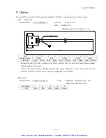
Page 22: ...lack Because the cable of which insulator color is blue and line color is black is not used please connect with the ground of the upper Connect the unused cables with the ground of the upper Otherwise...

Page 23: ...No QT33 04003A 17 Artisan Technology Group Quality Instrumentation Guaranteed 888 88 SOURCE www artisantg com...

Page 24: ...service in house repair center WE BUY USED EQUIPMENT Sell your excess underutilized and idle used equipment We also offer credit for buy backs and trade ins www artisantg com WeBuyEquipment REMOTE IN...

Reviews: