Mydax, Inc.
1M150W
Water Cooled Chiller
Designed for Lockheed Martin
6
INSTALLATION
POWER CONNECTION
Main electrical power connections to this system are made via a ten foot long power cord with a CS8165C plug.
This chiller requires a 50 amp circuit, 460/480 volt, 60 Hz, 3 phase.
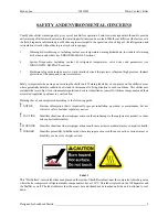
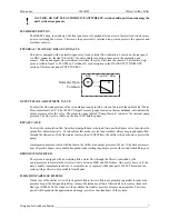
DANGER: Prior to any electrical servicing inside either the power box or the chiller cabinet,
disconnect the power cord and lockout the main breaker with a lockout device.
Once the unit is wired and plugged in, turn on the main circuit breakers mounted on the front of the system.
The unit will not run without the proper phase wiring, if the display flashes “AC Power Fault”, unplug the cord
and swap two of the phase lines and re-check.
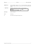
A message similar to the following appears on the 2 by 40-character main display:
This display indicates that the microprocessor is initializing. After a few seconds, the controller will finish
initializing and the "Warm-up Delay" message will return to simply "Mydax". Leave the unit turned on while
hooking up the following plumbing connections. This will allow time for the crankcase heater to warm the
compressor and separate the oil from the refrigerant.
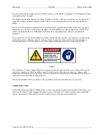
WARNING:
The system should be powered for a period of 1 hour before starting, to
allow the crankcase heater to separate the refrigerant from the oil.
CONDENSER FLOW
The condenser inlet and outlet fittings are 1" stainless steel female pipe thread fittings (FPT). Plumb the
facilities cooling water supply to the fitting marked
CONDENSER IN
. Plumb the facilities water return line to
the
CONDENSER OUT
connection. Given a facilities inlet temperature of +70
°
F, this chiller requires a flow
of up to 14 gallons per minute.
PLUMBING INTERFACE CONNECTIONS
The chiller's 2" stainless steel FPT fitting labeled
TANK OUT
must be plumbed to the inlet of the device to be
cooled. The outlet of the device to be cooled must be plumbed to the chiller's 2" FPT fitting labeled
TANK IN
.
This system is equipped with a 1/2" FPT fitting labeled
DRAIN
. A valve should be installed at this location
prior to the initial filling of the reservoir, for the convenience of future draining procedures. The recirculating
loop is under pressure when the system is operating.
Check all fluid interface connections now to ensure against leaks.
FILL RESERVOIR
This unit is designed to recirculate deionized water. To fill the system's reservoir, use a funnel or insert a hose
in the 1-1/2" fill port on the top of the reservoir and fill until the “Fill Tank” message is not present. Add
approximately 2 gallons of fluid after the “Fill Tank” message goes away to avoid nuisance alarms.
!
Tank --- Warmup Delay --- Local Set
12.10°C 0.0 Gpm 400K
Ω
12.0°C
!


