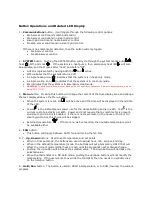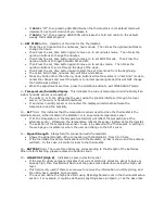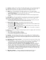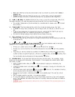
background image


On

 means that the fan has been manually turned on and will run until turned to 

Auto

 or 

Smart

 mode. 


Smart

 indicates that the Smart Fan mode is on.  Smart mode is like an intermittent 

windshield wiper and will run intermittently based on our optimal control algorithm. 

 
22 – 

%RH / (AM/PM)

: the AM/PM time for 12-hour clock, as well as a single circle of the % for 

the degree symbol (

°

) for external temp and percent symbol (%) for external humidity.   


The outdoor temperature (

°

) and humidity (%) will alternate for display when 

 (in field 

25) is chosen. 

 
23 – 

“€£$¥/kWh” 

This field indicates the unit for the 7-segment display above this field.   


If POWER is being shown, display the current usage in kW, for instance, 0.82 kW or 1.32 
kW.   


If Cost is being displayed, the appropriate currency symbol and the “/kWh” will be lit to 
indicate price-per-kWh, for instance, $0.07/kWh or $1.02/kWh. 


The order of denominations is Euro, British Pound, Dollar, Yuan/Yen. 
 

24 – 

Days of Week

: This will only be active when Clock is selected in field 25.   


Each two-character day of the week is a single element and will be lit according to what day 
of the week it is. 


25 –

Pwr

/Cost / Clk 

/Ext Temp+Humidity

.

 This field indicates what is currently 

displayed in the 7-segment display in the center of the LCD. 


If there is no smart meter, then Pwr 

and Cost   will not be available. 


If there is no web connection, then outside temphumidity 

 won’t be available 

either. 


Depending on which variables are available, the MENU button will have the corresponding 

number of items to cycle through (i.e., if there’s no smart-meter, and Clk 

 is active, then 

the next button-press will make Ext Temp+Humidity 

 active. 

 
26 – 

SYSTEM field

.  The System field will show the active system mode.  The available modes 

depend on the equipment controlled by the thermostat.  The complete list includes AUTO, HEAT, 
OFF, COOL, and EM.   


Heat is indicated with a flame icon ( ).  It is available if heating is controlled by the 
thermostat. 


Cooling is indicated with a snowflake icon (

).  It is available if cooling is controlled by the 

thermostat. 


AUTO is indicated with both flame ( ) and snowflake (

) icons lit.  It is available if heating 

and cooling are both controlled by the thermostat. 


Emergency heat mode is indicated with EM .  It is available only if the user has a heat 
pump. 


OFF is indicated with the text OFF.  It is always available. 


To see what mode is currently active when in Auto mode, look to the icons in the Setpoint 
area.  The snowflake will indicate the system is in cooling mode and the flame will indicate 
heating mode. 


CAUTION: 

To avoid possible compressor damage, do not use Auto Changeover if the outside temperature drops 

below 50°F (10°C). 


Summary of Contents for MyE Smart Home Gateway

Page 1: ...MyE Home Energy Management System Manual Front view of the thermostat LCD Display 1 2 3 4 5 6 7 8 9 10 11 12 13 14 15 16 17 18 19 20 21 25 26 27 28 22 23 24 ...

Page 2: ...e text displayed above the Menu button When the system is reset Clk will be active and the time will be displayed in the middle of the LCD Power is the instantaneous power use for the whole building and is in kWh Cost is the current cost of electricity per kWh Power and Cost require that a smart meter is present and smart grid control is enabled If there is no smart meter in the house or there is ...

Page 3: ...eld interface If an indoor humidity sensor is connected the display will alternate between the temperature and the humidity 10 ALT field This indicates that the temperature sensor used to drive the thermostat is the alternate sensor either located in the Mediator or in an external temperature sensor If lit the temperature in the temperature field 9 will reflect the temperature at the alternate sen...

Page 4: ...l blink 18 Stg 1 2 indicates what stage s heating cooling the system is engaged when the home has two stage systems Stg 1 means only the first stage is engaged Stg 1 2 means that both stages are engaged If the system is single stage then this field is inactive 19 Aux Heat This field indicates that the system is using auxiliary heat This field is active when the heat pump if one is present cannot p...

Page 5: ...he center of the LCD If there is no smart meter then Pwr and Cost will not be available If there is no web connection then outside temperature humidity won t be available either Depending on which variables are available the MENU button will have the corresponding number of items to cycle through i e if there s no smart meter and Clk is active then the next button press will make Ext Temp Humidity...

Page 6: ...d the AM PM units should begin flashing Set the AM PM by using the Up and Down buttons Press Set Time button again and the current active day will begin flashing Pressing the Up Down buttons will flash the next day previous day respectively At this point pressing the Set Time button again will start the cycle again by flashing the Hour units and so on Only when Hold Run is pressed is the change ac...

Page 7: ...Grid Mediator Without a connection to the Mediator the thermostat will not be able to have internet connection If the connection between the Mediator and Thermostat cannot be established then the signal strength icon will show 3 empty bars and the antenna will flash Smart Grid The Smart Grid connection is used by the Utility to send pricing messages and Demand Response events to the thermostat Thi...

Page 8: ...on displayed on the screen When locked the LOCK icon will be visible Specifications 1 MyETM Smart Home Gateway Physicaldimension 143 x 88 x 25 mm Power Supply DC5V 500mA Wireless ZIGBEE PRO 2 4G IEEEE 802 15 4 Compliant RF MAX Output power 4 5dBm Compliance FCC CFR47 Part15 RF Frequency Range 2394 2507 MHz Receiver Sensitivity 90dBm IEEE 802 3 10BASE T 100BASE TX Ethernet 10 100 Ethernet PHY inter...

Page 9: ...on reception which can be determined by turning the equipment off and on the user is encouraged to try to correct the interference by one or more of the following measures Reorient or relocate the receiving antenna Increase the distance between the equipment and receiver Connect the equipment to an outlet on a circuit different from that to which the receiver is connected Consult the dealer or an ...

Reviews: