background image

24


114794F – Install/User Manual


Summary of Contents for EM Series

Page 1: ...ION USER S GUIDE 1000W 2800W SINGLE PHASE Series EM EMERGENCY LIGHTING CENTRAL INVERTER Myers Emergency Power Systems 44 South Commerce Way Bethlehem PA 18017 1 800 526 5088 610 868 3500 Fax 610 868 8686 Service 610 868 5400 www myerseps com ...

Page 2: ...type batteries contain either acid or alkali and can cause burns to skin and eyes If battery fluid is spilled on skin or in the eyes flush with fresh water and contact a physician immediately 5 Equipment should be mounted in locations where it will not be subjected to tampering by unauthorized personnel 6 The use of accessory equipment not recommended by Manufacturer may cause an unsafe condition ...

Page 3: ...ION TELEPHONE 610 868 5400 24 HR HOTLINE FAX 610 954 8227 FOR YOUR PROTECTION PLEASE COMPLETE AND RETURN WARRANTY REGISTRATION CARD IMMEDIATELY CAUTION Do not drill the cabinet drilling cabinet will void factory warranty drill filings may damage the unit and keep it from operating If you need larger knockouts use a chassis punch to punch out the appropriate knockout ...

Page 4: ... connecting the batteries Replacing the batteries Battery Interconnect drawings SECTION 6 Startup and shutdown procedure 30 31 SECTION 7 Operation 32 SECTION 8 Keypad Front Display Panel 33 36 Control panel keypads Meter functions Control functions Program functions Automatic tests SECTION 9 RS232 Operation 37 47 SECTION 10 Option Drawings 48 56 Floor Base Floor Mount Anchor Bolts Drip Top Battery...

Page 5: ...ment for other than intended use Only qualified service personnel such as a licensed electrician should perform the system and battery installation and initial startup Risk of electrical shock BATTERY STORAGE This shipment contains rechargeable maintenance free batteries They must be stored properly to assure proper operation upon installation Therefore please follow the following guidelines when ...

Page 6: ...is feature protects the battery from being permanently damaged from a deep discharge that could cause cell reversal This battery protection feature is called Low Voltage Disconnect or L V D When the AC power is restored after a full discharge the system will be ready for another power failure within 24hrs If another power failure occurs before the 24 hour recharge time the run time will be decreas...

Page 7: ...the inspection testing and maintenance A note of any unsatisfactory condition observed or discovered and the steps taken to correct the condition Service and Support We are committed to outstanding customer service A service technician is available 24 hours a day 365 days a year Service is also available 24 hours a day to give you access to technical notes and product information NOTE Please have ...

Page 8: ...d Weights Figure 3 1 1000W System Dimensions Figure 3 2 1600W 2200W System Dimensions Required Clearance Top 6 15 24 cm Sides 2 5 1 cm Front 36 91 4 cm Required Clearance Top 6 15 24 cm Sides 2 5 1 cm Front 36 91 4 cm Shown with Optional Floor Mount Base Shown with Optional Floor Mount Base ...

Page 9: ...stem weight in lbs kg 1000W 1600W 2200W 2800W Inverter Cabinet 121 55 165 75 174 79 203 92 Batteries 160 73 240 109 320 146 400 182 System Total 281 128 405 184 494 225 603 274 Shown with Optional Floor Mount Base Required Clearance Top 6 15 24 cm Sides 2 5 1 cm Front 36 91 4 cm ...

Page 10: ...14794F Install User Manual Knockout Diameter 7 8 1 1 8 2 2 cm 2 9 cm Figure 3 4 Conduit Knockout Dimensions Stacking Detail for Systems with a Battery Cabinet Figure 3 5 Cabinet Stacking Detail 1600W 2800W ...

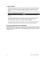
Page 11: ...ed CEC Canadian Electric Code requires the unit to be located in a service room If the room is equipped with a sprinkler system the unit must be provided with sprinkler proof cover The system should be connected to the emergency generator if available This equipment is heavy Refer to Table 3 1 when you choose a site to make sure that the floor can support the weight of the system the batteries and...

Page 12: ... would be at a normal temperature of 25 C 77 F At about 45 C 113 F battery life is one fourth of normal Make sure that heaters sunlight air conditioners or outside air vents are not directed toward the batteries These conditions can make the temperature within battery strings vary which can cause differences in the batteries voltages Eventually these conditions affect battery performance Do not al...

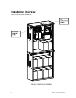
Page 13: ...12 114794F Install User Manual Installation Overview Figure 3 6 shows typical installations Figure 3 6 Typical Hardwire Installation BUILDING SERVICE PANEL TO SUPPORTED LOADS ...

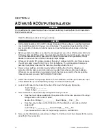
Page 14: ... injury always assume that there may be voltage inside the unit Remove rings watches and other jewelry before installing the AC wiring Always wear protective clothing and eye protection and use insulated tools when working near batteries Whenever you are servicing an energized unit with the door open electric shock is possible follow all local safety codes TEST BEFORE TOUCHING 1 Remove the cabinet...

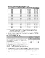
Page 15: ...roper gauge wire for the recommended circuit breaker recorded in step 5 Table 4 2 Recommended Minimum Wire Sizes Read These Important Notes For this Input Circuit Breaker Size Use this Size 90 C Copper Wire This table lists the AWG and mm2 wire size for each circuit breaker size The minimum recommended circuit breaker sizes for each model and voltage application are listed in Table 4 1 The tempera...

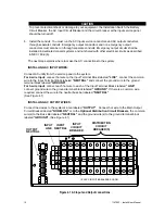
Page 16: ...m For 2 wire input connect hot wire to the Input Terminal Block labeled LINE connect the common wire to the Input Terminal Block labeled NEUTRAL and connect the ground wire to the ground terminal block labeled GROUND For 3 wire input connect each hot wire to each of the Input Terminal Blocks labeled LINE connect ground wire to the ground terminal block labeled GROUND If there is a common wire requ...

Page 17: ...ter positive Safety Instructions IMPORTANT SAFETY INSTRUCTIONS SAVE THESE INSTRUCTIONS This section contains important instructions that a qualified service person should follow during installation and maintenance of the system and batteries ONLY a qualified service person should work with the batteries CAUTION Full voltage and current are always present at the battery terminals The batteries used...

Page 18: ... terminals so that the cable lug does not contact any part of the cabinet even if the battery is moved Keep the cable away from any sharp metal edges CAUTION If you are replacing batteries or repairing battery connections follow the procedure in the section 6 to shut down your system and remove both AC and DC input power Before Installing the Batteries Tools CAUTION Always use insulated tools when...

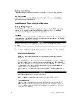
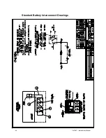
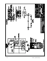
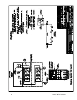
Page 19: ...d To make sure a location is acceptable for the system review the requirements in Section 3 Arranging the Batteries NOTE As you arrange the batteries you must be wearing the required safety equipment Arrange the batteries in the cabinet only as shown in the battery wiring diagram This arrangement is designed to maximize airflow around the batteries The cabinets are designed so that battery cases s...

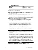
Page 20: ...tery temperature probe labeled TEMP PROBE to the front battery terminal on the second battery in from the right on the top shelf See Table 5 2 Torque the connections to the value shown for your battery in Table 5 1 3 Connect the battery cables from one shelf to the next as shown on the battery wiring diagram 1600W 2800W Systems only CAUTION Hazardous voltage is present System batteries are high cu...

Page 21: ...Blocks and Battery Circuit Breaker Table 5 2 Battery Temperature Probe Placements Models 1000W 1600W 2200W 2800W Battery Volts 36v 60v 84v 96v Battery number from battery wiring diagram 3 Terminal 5 Terminal 7 Terminal 9 Terminal BATTERY CIRCUIT BREAKER NEG POS ...

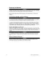
Page 22: ... the same number of batteries These batteries must be the same types as the original batteries The replacement batteries should have the same voltage and ampere hour rating as the original batteries Handle Used Batteries with Care Assume that old batteries are fully charged Use the same precautions you would use when handling a new battery Do not short battery terminals or the battery string with ...

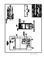
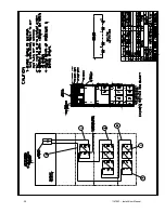
Page 23: ...22 114794F Install User Manual Standard Battery Interconnect Drawings ...

Page 24: ...23 114794F Install User Manual ...

Page 25: ...24 114794F Install User Manual ...

Page 26: ...25 114794F Install User Manual ...

Page 27: ...26 114794F Install User Manual Optional Battery Interconnect Drawings ...

Page 28: ...27 114794F Install User Manual ...

Page 29: ...28 114794F Install User Manual ...

Page 30: ...29 114794F Install User Manual ...

Page 31: ... Breaker are OFF 2 Turn on AC input at the building service center 3 Locate the DC Pre charge Switch see figure 6 1 press it for five seconds then turn ON the Battery Circuit Breaker If a large flash occurs the batteries are not connected properly Call service immediately 4 Turn ON the Main AC Input Circuit Breaker See figure 4 1 5 Turn the installation switch to the ON position System will run on...

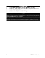
Page 32: ...Discharge Switch see figure 6 1 press it for 10 seconds 5 Turn OFF the Main AC Input Circuit Breaker See Figure 4 1 CAUTION HAZARDOUS VOLTAGES STILL EXIST AT THE BATTERY TERMINAL CONNECTIONS AND WITHIN THE SYSTEM AUTHORIZED SERVICE TECHNICIANS MUST DISCHARGE DC CAPACITORS AND TURN OFF UTILITY POWER BEFORE SERVICING EQUIPMENT DO NOT LEAVE THE SYSTEM SHUTDOWN FOR A PROLONGED LENGTH OF TIME LEAD BASE...

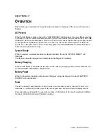
Page 33: ...t the inverter would be running System Ready When the system has adequate battery voltage to transfer the words SYSTEM READY will illuminate This feature prevents damage from multiple deep discharges of the battery Battery Charging When the AC Mains is connected to the line and the battery is charging under normal conditions the words BATTERY CHARGING will illuminate Battery Power When the inverte...

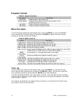
Page 34: ...tions from the default screen press the ENTER key and then press the left or the right arrow key to go to the desired menu The Menu s available are Meter Test Log Event Log Alarm Log User Setup Factory Setup Status System Information and Test Mode Once the desired menu has been reached press the ENTER key to gain access to this menu Once into the menu use the left or right arrow key to scroll to d...

Page 35: ...l be positive When in Inverter mode the current will be negative Battery Temperature Optional feature measures temperature at the battery Internal Temperature Measures the ambient temperature inside the system Inverter Minutes Indicates the total minutes the system has run on inverter System Days Indicates the total days the system has been on line VA Output Indicates the AC Volts Amps of the Inve...

Page 36: ... from the default screen press the ENTER key scroll the Alarm menu using the left or right arrow key then press the ENTER key again The alarm menu displays all present alarms If there are no alarms the display screen will indicate no alarms User Setup To get to the User Setup menu from the default screen press the ENTER key scroll to the User Setup menu using the left or right arrow key then press...

Page 37: ...tery Fault Chart DC Voltage Near Low Battery 48VDC 43VDC 72VDC 65VDC 96VDC 86VDC 120VDC 108VDC Load Reduction Current Parameters are set in Amps AC Use the same technique as the above alarms for modification Load Reduction Current is a useful diagnostic tool that will automatically generate a fault when the output current is 10 percent higher or lower than the set point number Status Indicates the...

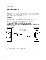
Page 38: ... Installation Guide for the exact location of the connector The Connector between the computer and the Inverter is a straight connection Do not use a Null Modem Cable that flips pins 2 and 3 Pin 2 and Pin 3 are the Data send and receive lines Pin 5 is the Ground Optical isolation on the Interface card provides galvanic isolation between the computers ground and the Inverters ground PC Connector DB...

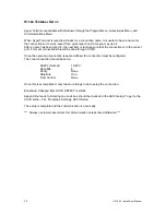
Page 39: ...r most connections this will be done through COM1 Once the name and connection type are defined the connection must be configured The Local connection should be set to Bits Per Second 19 200 Data Bits 8 Parity None Stop Bits One Flow Control None Once this is accomplished only two more things to do to setup the connection Emulation Changed from AUTO DETECT to ANSI Append line feeds to incoming lin...

Page 40: ...d prompt CMD appears then the user can then query the machine The command prompt CMD Once communication is established all characters will be echoed back to the computer and the monitor will display what characters the user sends Help screen Once the shell command is executed and the command prompt appears the user may type help for a listing of various commands available to the user Now that comm...

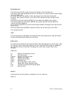
Page 41: ...sabled Charger Fault faxes report Disabled Output Fault faxes report Disabled Overload faxes report Disabled Overload Shutdown faxes report Disabled High Ambient faxes report Disabled High VAC faxes report Disabled Low VAC faxes report Disabled Low Battery faxes report Disabled Near Low Battery faxes report Disabled Utility faxes report Disabled Load Reduction faxes report Disabled Runtime faxes r...

Page 42: ...age alarm to 105 VAC type lvac and then tab and type 105 and then tab and then type on or off to turn the alarm on or off Example CMD setpoint lvac 105 on Notice how there is a space between the word set point and lvac The TAB character achieved this space When the user presses TAB a character is sent to the interface this character inserts the space and also uses the TAB character as a delimiter ...

Page 43: ...rms Inverter 0 Charger 0 Output 0 Overload 0 Overload Shutdown 0 High Ambient 0 High VAC 0 Low VAC 0 Low Battery 0 Near Low Battery 0 Utility 0 Load Reduction 0 Runtime 0 Circuit Breaker 0 Overtemp 0 The format is binary A 1 indicates that the alarm is present a 0 indicates that no alarm is present Alarms Events and Tests Dump The dump command displays all of the memory content for Events Tests or...

Page 44: ... 12 3 day of month 1 31 4 year 0 99 5 hours 0 23 6 minutes 0 59 TUE AUG 10 2004 11 03 57 The Parameter day of week is 1 and its data is 1 through 7 1 is Sunday and then the days follow in sequential order To change the parameter type the dt command then the tab and then the parameter number and then the tab and then the parameter information The tab is used as a delimiter between the commands and ...

Page 45: ...AT enter until the message OK appears Type the following AT commands ATM1 enter speaker on until connected AT D0 enter ignore DTR AT K0 enter no flow control ATS0 1 enter auto answer after one ring AT W0 store to non volatile memory DIALING THE ZOOM MODEM Type AT enter until the message OK appears Type for example ATD9 16109545224 enter ATD is the command 9 16109545224 is the phone number 9 for ou...

Page 46: ...45 114794F Install User Manual LOCATION OF THE RS232 PORT Figure 9 2 PHONE LINE HOOKUP FOR E MAIL MODEM OPTION RS232 PORT BEHIND FRONT PANEL ...

Page 47: ...46 114794F Install User Manual Figure 9 3 ...

Page 48: ...47 114794F Install User Manual Figure 9 4 ...

Page 49: ...48 114794F Install User Manual SECTION 10 OPTION DRAWINGS ...

Page 50: ...49 114794F Install User Manual ...

Page 51: ...50 114794F Install User Manual ...

Page 52: ...51 114794F Install User Manual ...

Page 53: ...52 114794F Install User Manual ...

Page 54: ...53 114794F Install User Manual ...

Page 55: ...54 114794F Install User Manual ...

Page 56: ...55 114794F Install User Manual CENTRAL EMERGENCY SYSTEM FAULT ALARM ...

Page 57: ...56 114794F Install User Manual ...

Page 58: ...et above sea level without derating Operating Temperature 20 to 30 degree Celsius Storage Temperature 20 to 70 degrees Celsius electronics only Relative Humidity 95 non condensing General Design Line interactive PWM inverter type utilizing IGBT technology with 2mS transfer time Generator Input Compatible with generators Control Panel Microprocessor controlled 4 x 20 charactor vacuum fluorescent di...

Page 59: ...ir vents free of any obstruction If the environment tends to be extremely dusty occasionally blow away any accumulation of dust on components Please follow the shutdown procedure before cleaning CAUTION Follow the shutdown procedure See Section 6 before cleaning An authorized technician only should perform Service Table 12 1 Preventive Maintenance Schedule SERVICE TO PERFORM PERFORM SERVICE EVERY ...

Page 60: ...failure 3 2 1 4 System noisy excessive transformer hum during normal run conditions 1 2 3 System draws excessive AC input current 1 2 3 Inverter will not run during a power failure 1 3 4 6 2 11 7 10 9 8 5 S Y M P T O M S Installation switch on inverter in off position S h o r t e d I G B T m o d u l e s No AC input voltage D e f e c t i v e i n v e r t e r Output volt ampere rating of unit being e...

Page 61: ...60 114794F Install User Manual ...
Page 62: ...eemed necessary to return material the RMA number must appear on shipping labels packing slips and bills of lading OUT OF WARRANTY REPAIR CHARGES AND LABOR Contact Field service for current parts and labor rates A minimum rate will be assessed The manufacturer will not proceed with repairs of an out of warranty unit until authorization in the form of a purchase order is received from the customer ...

Page 63: ...ts of nature such as but not limited to lightning flooding explosions and earthquakes are not covered The warranty is limited to the repair and or replacement of parts and or units that upon examination at our factory and or job site are determined to be defective and in our judgment are subject to repair or replacement All such repair shall be manufacturer s exclusive remedy A date code part numb...

Page 64: ...han 30 days annually E Battery service records must be maintained F Batteries must be installed and energized within 180 days of shipment G System warranty registration card must be filled out and returned to the manufacturer upon installation If any battery fails to deliver 80 of its capacity within the 10 year warranty period the manufacturer at its option will repair or replace it on a prorated...

Reviews: