32
114794F – Install/User Manual
SECTION
7
O
PERATION
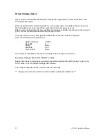
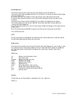
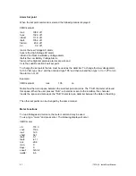
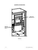
The following is a description of the system status located on the panel of the Vacuum Fluorescent
Display.
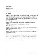
AC Present
When the AC Mains is present, the words “LINE PRESENT” will illuminate. If a power failure was long
in duration, or the AC mains was disconnected by some other means (Circuit breaker open) the “LINE
PRESENT” would not be illuminated. When the control circuit senses that the line has dropped below
an acceptable level (Black Out, Brown Out, or Transient), the inverter will energize for at least one
minute. So, if the power failure was a momentary glitch, the “LINE PRESENT” would be illuminated
but the inverter would be running.
System Ready
When the system has adequate battery voltage to transfer, the words “SYSTEM READY” will
illuminate.
This feature prevents damage from multiple deep discharges of the battery.
Battery Charging
When the AC Mains is connected to the line and the battery is charging under normal conditions, the
words “BATTERY CHARGING” will illuminate.
Battery Power
When the inverter is producing output power (battery is being discharged), the words “BATTERY
POWER” will be illuminated.
Fault
This is a summary Fault indication. When there is a fault condition present, the word “FAULT” will
illuminate. To view which fault is present, use the keypad and vacuum fluorescent display feature.
The panel display will provide the user with a variety of information. It has a full compliment of Meter
functions, Control functions and Program functions.
Summary of Contents for EM Series
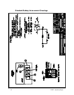
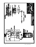
Page 23: ...22 114794F Install User Manual Standard Battery Interconnect Drawings ...
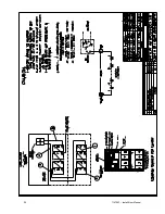
Page 24: ...23 114794F Install User Manual ...
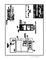
Page 25: ...24 114794F Install User Manual ...
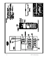
Page 26: ...25 114794F Install User Manual ...
Page 27: ...26 114794F Install User Manual Optional Battery Interconnect Drawings ...
Page 28: ...27 114794F Install User Manual ...
Page 29: ...28 114794F Install User Manual ...
Page 30: ...29 114794F Install User Manual ...
Page 47: ...46 114794F Install User Manual Figure 9 3 ...
Page 48: ...47 114794F Install User Manual Figure 9 4 ...
Page 49: ...48 114794F Install User Manual SECTION 10 OPTION DRAWINGS ...
Page 50: ...49 114794F Install User Manual ...
Page 51: ...50 114794F Install User Manual ...
Page 52: ...51 114794F Install User Manual ...
Page 53: ...52 114794F Install User Manual ...
Page 54: ...53 114794F Install User Manual ...
Page 55: ...54 114794F Install User Manual ...
Page 56: ...55 114794F Install User Manual CENTRAL EMERGENCY SYSTEM FAULT ALARM ...
Page 57: ...56 114794F Install User Manual ...

