37
114794F - Install/User Manual
SECTION 9
RS232
O
PERATION
I
NTRODUCTION
:
This is intended to explain the operation and communication protocol for the Emergency Lighting
Central Inverter. Serial Communication can be established by means of a computer using Hyper-
Link windows based software or using a Terminal device.
C
ONNECTION
:
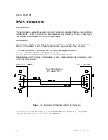
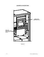
The Central Inverter has a 9 pin Sub-D Female connector located on the front panel located on
the door of the inverter. See the Installation Guide for the exact location of the connector.
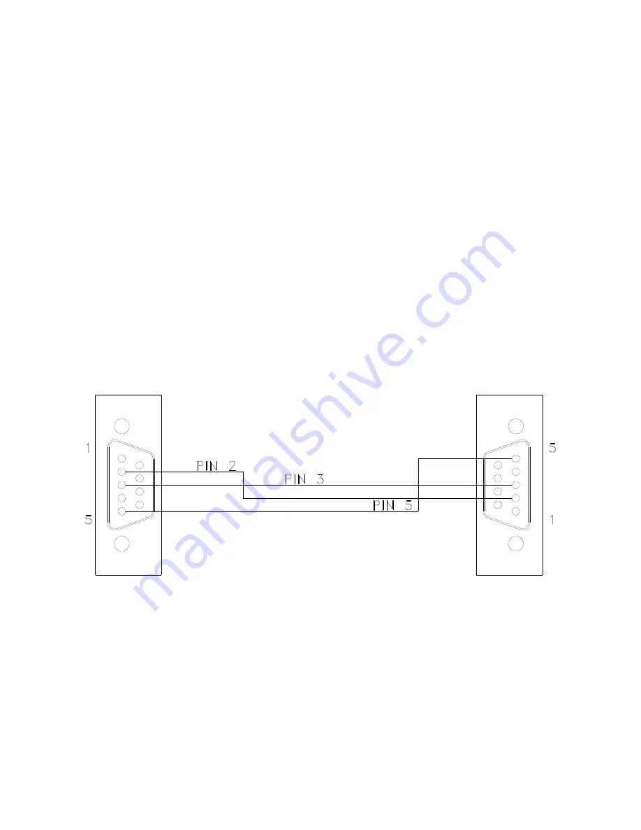
The Connector between the computer and the Inverter is a straight connection.
Do not use a Null Modem Cable that flips pins 2 and 3.
Pin 2 and Pin 3 are the Data send and receive lines; Pin 5 is the Ground.
Optical isolation on the Interface card provides galvanic isolation between the computers ground
and the Inverters ground.
PC
Connector
DB-9
Connector
DB-9
Straight Connection
Pins used = 2,3 5
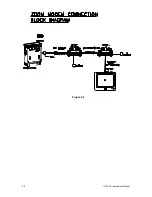
Figure 9.1
– Interconnect Schematic for RS-232 Connection
Communication is established through a standard ASCII format of 8 Data bits, 1 Stop bit, No
parity, No Flow Control, and a Baud rate of 19,200 BPS.
Summary of Contents for EM Series
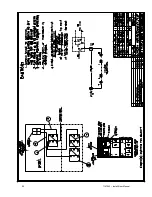
Page 23: ...22 114794F Install User Manual Standard Battery Interconnect Drawings ...
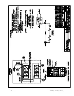
Page 24: ...23 114794F Install User Manual ...
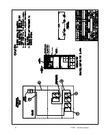
Page 25: ...24 114794F Install User Manual ...
Page 26: ...25 114794F Install User Manual ...
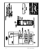
Page 27: ...26 114794F Install User Manual Optional Battery Interconnect Drawings ...
Page 28: ...27 114794F Install User Manual ...
Page 29: ...28 114794F Install User Manual ...
Page 30: ...29 114794F Install User Manual ...
Page 47: ...46 114794F Install User Manual Figure 9 3 ...
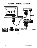
Page 48: ...47 114794F Install User Manual Figure 9 4 ...
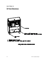
Page 49: ...48 114794F Install User Manual SECTION 10 OPTION DRAWINGS ...
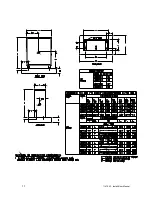
Page 50: ...49 114794F Install User Manual ...
Page 51: ...50 114794F Install User Manual ...
Page 52: ...51 114794F Install User Manual ...
Page 53: ...52 114794F Install User Manual ...
Page 54: ...53 114794F Install User Manual ...
Page 55: ...54 114794F Install User Manual ...
Page 56: ...55 114794F Install User Manual CENTRAL EMERGENCY SYSTEM FAULT ALARM ...
Page 57: ...56 114794F Install User Manual ...

