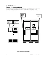
114061H System Installation Manual
11
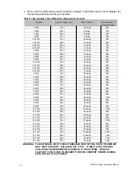
5. Write down the circuit breaker value that applies to your system from Table 5.1:
__________
6. Now, look at Table 5.2 below, and use the notes below to find the proper gauge wire
for the recommended circuit breaker recorded in step 5.
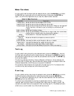
Table 5.2 Recommended Minimum Wire Sizes
Read These Important Notes!
For this Input
Circuit Breaker
Size...
Use this Size 90°C
Copper Wire
This table lists the AWG and mm2 wire size for each circuit breaker size.
The minimum recommended circuit breaker sizes for each model and
voltage application are listed in Table 5.1. The temperature rating of
conductor must not be less than 90° C wire. Based on the ampacities
given in Tables 310-16 of the National Electrical Code, ANSI/NFPA 70-
1993 (Table 2 of the CEC), and NEC article 220 (CEC Section 4). Circuit
conductors, must be the same size (ampacity) wires and equipment-
grounding conductors must meet Table 250-95 of the National Electrical
Code. Code may require a larger wire size than shown in this table
because of temperature, number of conductors in the conduit, or long
service runs. Follow local code requirements.
AWG
Mm2
10, 15, 20
12
3.31
25, 30
10
5.26
35, 40, 45
8
8.36
50, 60
6
13.30
70, 80
4
21.15
90, 100
2
33.62
110
1
42.11
125
1/0
53.49
150, 175
3/0
67.43
225
4/0
74.40
7. The input circuit breaker in the input service panel provides the means for disconnecting AC
to the unit. Only authorized persons shall be able to disconnect AC to the unit [see NEC 700-20
and 700-21(CEC Section 46)]. If you are using the input circuit breaker to disconnect AC, you
must make sure that only authorized persons have control of the circuit breaker panel to meet
the requirements of NEC 700-20 (CEC Section 46).
8
. Read the following caution, before removing conduit knockouts.
CAUTION
To prevent electrical shock or damage to your equipment, the Installation Switch (S1), the Main
AC Input Circuit Breaker (CB1), and the circuit breaker at the input service panel should all be
turned off. The Main DC Battery Fuse and the Battery Disconnect Fuse(s) (if you have one)
should be removed.
9
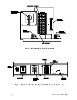
. Remove knockouts for AC Input and AC Output in the top or left and right side of the system
(See figure 4.1). AC input conductors and AC output conductors must be installed in separate
conduits, and emergency and non-emergency output circuits must be installed in separate
conduits.
CAUTION
Do not drill the cabinet; drill filings may damage the unit and keep it from operating. If you
need larger knockouts, use a chassis punch to punch out the appropriate knockout. Do not
create additional knockouts
.
10. Install the conduit. You must run the AC input service conductors and AC output conductors
through separate conduits. Emergency output conductors and non-emergency output conductors
must also be run through separate conduits. Emergency output circuits shall be installed in
dedicated conduit systems and not shared with other electrical circuits as described in NEC 700-
9(b) [CEC Section 47-108].


