99
115895B System Installation Manual
SERIAL TO ETHERNET ADAPTER OPTION SECTION
(for example, a Wired LAN Interface, and a Wireless (WiFi) LAN Interface), be
sure to only change these settings on the correct Wired LAN Interface.
3.
Open a web browser window, and enter
“
10.16.0.67
”
in the
“
Address
”
bar.
4.
The login page of the IOLAN SDG1 will load. Enter
“
admin
”
as the Username, and
“
superuser
”
as the Password.
5.
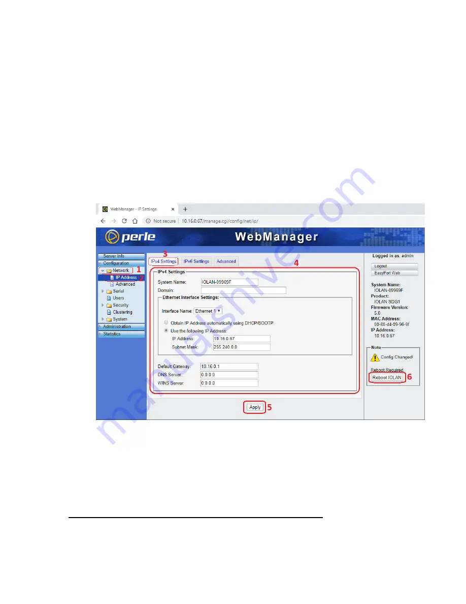
On the navigation frame (left column), click the word
“
Network
”
(with an icon of
a yellow folder to the left of it). This will expand the
“
Network
”
menu.
6.
Click the word
“
IP Address
”
in the expanded
“
Network
”
menu.
7.
Click on the
“
IPv4 Settings
”
tab if it is not already selected.
8.
Set the IP address, Subnet Mask, and Default Gateway you wish to assign the
IOLAN SDG1 to work on your LAN. Note: Entering a static IP address is highly
recommended, even if your LAN includes a DHCP (dynamic IP) server, because
with DHCP your IOLAN SDG1 might periodically change IP address.
9.
Click the Apply button
10.
Click the
“
Reboot IOLAN
”
button that just appeared in the bottom right
11.
Close your web browser window
12.
Disconnect the Ethernet cable between your PC and the IOLAN SDG1
13.
Restore the previous IP settings for the wired LAN interface on your PC
14.
Connect the IOLAN SDG1 ethernet port to your LAN
15.
We recommend you stick a label on the IOLAN SDG1
–
or on the outside of your
inverter cabinet
–
listing the IP address and subnet mask you set the device up
with. This may prove very useful to you or someone else in future.
2 - Communicating with Your Inverter Using an SSH Client
Your Serial to Ethernet Communication Interface is now ready for SSH
communication with your Myers EPS Emergency Lighting Central Inverter, using the IP
address you set in Section 1 above, and SSH on port
2222
. If you would like to change
Summary of Contents for Illuminator Supernova Series
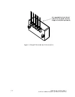
Page 16: ...15 115895B System Installation Manual Figure 5 2 AC Connections for 6 25 k W 7 5 kW systems ...
Page 17: ...16 115895B System Installation Manual Figure 5 3 AC Connections for 10 kW 16 7 kW systems ...
Page 30: ...115895B System Installation Manual PART II OPTIONS MANUALS Section continues on next page ...
Page 95: ...94 115895B System Installation Manual SERIAL TO ETHERNET ADAPTER OPTION SECTION ...
Page 96: ...95 115895B System Installation Manual SERIAL TO ETHERNET ADAPTER OPTION SECTION ...
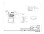
Page 114: ...113 115895B System Installation Manual DRAWINGS SECTION ...
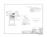
Page 115: ...114 115895B System Installation Manual DRAWINGS SECTION ...
Page 116: ...115 115895B System Installation Manual DRAWINGS SECTION ...
Page 117: ...116 115895B System Installation Manual DRAWINGS SECTION ...
Page 118: ...117 115895B System Installation Manual DRAWINGS SECTION ...
Page 119: ...118 115895B System Installation Manual DRAWINGS SECTION ...
Page 120: ...119 115895B System Installation Manual DRAWINGS SECTION ...
Page 121: ...120 115895B System Installation Manual DRAWINGS SECTION ...
Page 122: ...121 115895B System Installation Manual DRAWINGS SECTION ...
Page 123: ...122 115895B System Installation Manual DRAWINGS SECTION ...
Page 124: ...123 115895B System Installation Manual DRAWINGS SECTION ...
Page 125: ...124 115895B System Installation Manual DRAWINGS SECTION ...
Page 126: ...125 115895B System Installation Manual DRAWINGS SECTION ...
Page 127: ...126 115895B System Installation Manual DRAWINGS SECTION ...
Page 128: ...127 115895B System Installation Manual DRAWINGS SECTION ...
Page 129: ...128 115895B System Installation Manual DRAWINGS SECTION ...
Page 130: ...129 115895B System Installation Manual DRAWINGS SECTION ...
Page 131: ...130 115895B System Installation Manual Notes ...

