100
115895B System Installation Manual
SERIAL TO ETHERNET ADAPTER OPTION SECTION
the port number, or use Telnet instead of SSH, see sections 3 and 4 below (note that
SSH is highly recommended over Telnet, as it is encrypted while all Telnet
communications
–
including passwords
–
are cleartext).
Simply open your SSH Client software (for example, PuTTY is a completely free
and very lightweight SSH client, Windows 10 and newer includes a bundled OpenSSH
Client feature that can be enabled, etc.) and connect to the SSH server on the IOLAN
SDG1. The first time you do this from a given PC, the SSH Client will ask you if you wish
to accept the security key, and you must answer
‘
yes
’
. You will then be presented with a
login. Use
“
myerseps
”
as the username, and
“
inverter
”
as the password.
You should now be connected to your Myers EPS Emergency Lighting Central
Inverter, and ready to communicate with it using the Myers EPS RS-232 Communication
Protocol, as described in the RS-232 Protocol Manual. To find the right RS-232 Protocol
Manual in PDF format:
•
For Series-E or Series-IE inverters, Google
“
Myers EPS 114063 pdf
”
•
For Series-CI, Series-CIII, Series-CR, Series-DR or Series-SR inverters, Google
“
Myers EPS 113786 pdf
”
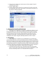
3 - Changing the Port Number
Depending on your organization
’
s IT policies, sometimes certain port numbers
may be firewalled (blocked) on your LAN, and so you might be asked by your IT/network
staff to change the port number used by this interface to a port number that is not
firewalled.
1.
Open a web browser window, type the IP address (that you set to your IOLAN
SDG1 in Section 1 above) in the
“
Address
”
bar, and press enter.
2.
The login page of the IOLAN SDG1 will load. Enter
“
admin
”
as the Username, and
“
superuser
”
as the Password.
3.
On the navigation frame (left column), click the word
“
Serial
”
(with an icon of a
yellow folder to the left of it). This will expand the
“
Serial
”
menu.
4.
Click the word
“
Serial Port
”
in the expanded
“
Serial
”
menu.
5.
One serial port should be highlighted in a table with one row. Click
“
Edit
…”
Summary of Contents for Illuminator Supernova Series
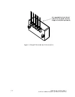
Page 16: ...15 115895B System Installation Manual Figure 5 2 AC Connections for 6 25 k W 7 5 kW systems ...
Page 17: ...16 115895B System Installation Manual Figure 5 3 AC Connections for 10 kW 16 7 kW systems ...
Page 30: ...115895B System Installation Manual PART II OPTIONS MANUALS Section continues on next page ...
Page 95: ...94 115895B System Installation Manual SERIAL TO ETHERNET ADAPTER OPTION SECTION ...
Page 96: ...95 115895B System Installation Manual SERIAL TO ETHERNET ADAPTER OPTION SECTION ...
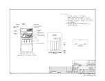
Page 114: ...113 115895B System Installation Manual DRAWINGS SECTION ...
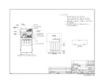
Page 115: ...114 115895B System Installation Manual DRAWINGS SECTION ...
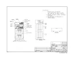
Page 116: ...115 115895B System Installation Manual DRAWINGS SECTION ...
Page 117: ...116 115895B System Installation Manual DRAWINGS SECTION ...
Page 118: ...117 115895B System Installation Manual DRAWINGS SECTION ...
Page 119: ...118 115895B System Installation Manual DRAWINGS SECTION ...
Page 120: ...119 115895B System Installation Manual DRAWINGS SECTION ...
Page 121: ...120 115895B System Installation Manual DRAWINGS SECTION ...
Page 122: ...121 115895B System Installation Manual DRAWINGS SECTION ...
Page 123: ...122 115895B System Installation Manual DRAWINGS SECTION ...
Page 124: ...123 115895B System Installation Manual DRAWINGS SECTION ...
Page 125: ...124 115895B System Installation Manual DRAWINGS SECTION ...
Page 126: ...125 115895B System Installation Manual DRAWINGS SECTION ...
Page 127: ...126 115895B System Installation Manual DRAWINGS SECTION ...
Page 128: ...127 115895B System Installation Manual DRAWINGS SECTION ...
Page 129: ...128 115895B System Installation Manual DRAWINGS SECTION ...
Page 130: ...129 115895B System Installation Manual DRAWINGS SECTION ...
Page 131: ...130 115895B System Installation Manual Notes ...

