104
115895B System Installation Manual
BATTERY THERMAL RUNAWAY SYSTEM OPTION SECTION
SECTION 1
System Description
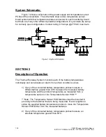
The Thermal Runaway Detection Option consists of two components. The first
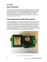
PCB component is the Power Supply Relay PCB that performs a summary dry
contact closure on an alarm from any of the temperature sensor boards. This
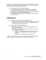
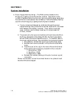
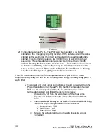
PCB is shown in Picture 1. The second PCB component is a Temperature
Sensor PCB that measures the temperature from each battery, runs an
algorithm, and sets an alarm if there is a troubling condition. The temperature
sensor PCB is shown in Picture 2.
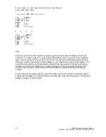
Power Supply/Summary Relay PCB connections
The Power Supply and Summary Alarm PCB can be identified by the assembly
number PCB404394XXX. The main power is supplied to the connector on the
left. If jumpers R4 and R5 are installed the input voltage required is 115vac. If
jumper R3 is installed then the input voltage is set up to accept a 230vac input.
Connector J2, in the center on the right side of the PCB is used to supply the
power to the Temperature Sensor PCB as well as collects the alarm trigger from
the Temperature Sensor PCB. The connectors on the right at the top and bottom
as shown provides the summary dry contacts for the alarm signal.
Picture 1
– Power Supply/Summary Relay PCB
Summary of Contents for Illuminator Supernova Series
Page 16: ...15 115895B System Installation Manual Figure 5 2 AC Connections for 6 25 k W 7 5 kW systems ...
Page 17: ...16 115895B System Installation Manual Figure 5 3 AC Connections for 10 kW 16 7 kW systems ...
Page 30: ...115895B System Installation Manual PART II OPTIONS MANUALS Section continues on next page ...
Page 95: ...94 115895B System Installation Manual SERIAL TO ETHERNET ADAPTER OPTION SECTION ...
Page 96: ...95 115895B System Installation Manual SERIAL TO ETHERNET ADAPTER OPTION SECTION ...
Page 114: ...113 115895B System Installation Manual DRAWINGS SECTION ...
Page 115: ...114 115895B System Installation Manual DRAWINGS SECTION ...
Page 116: ...115 115895B System Installation Manual DRAWINGS SECTION ...
Page 117: ...116 115895B System Installation Manual DRAWINGS SECTION ...
Page 118: ...117 115895B System Installation Manual DRAWINGS SECTION ...
Page 119: ...118 115895B System Installation Manual DRAWINGS SECTION ...
Page 120: ...119 115895B System Installation Manual DRAWINGS SECTION ...
Page 121: ...120 115895B System Installation Manual DRAWINGS SECTION ...
Page 122: ...121 115895B System Installation Manual DRAWINGS SECTION ...
Page 123: ...122 115895B System Installation Manual DRAWINGS SECTION ...
Page 124: ...123 115895B System Installation Manual DRAWINGS SECTION ...
Page 125: ...124 115895B System Installation Manual DRAWINGS SECTION ...
Page 126: ...125 115895B System Installation Manual DRAWINGS SECTION ...
Page 127: ...126 115895B System Installation Manual DRAWINGS SECTION ...
Page 128: ...127 115895B System Installation Manual DRAWINGS SECTION ...
Page 129: ...128 115895B System Installation Manual DRAWINGS SECTION ...
Page 130: ...129 115895B System Installation Manual DRAWINGS SECTION ...
Page 131: ...130 115895B System Installation Manual Notes ...

