105
115895B System Installation Manual
BATTERY THERMAL RUNAWAY SYSTEM OPTION SECTION
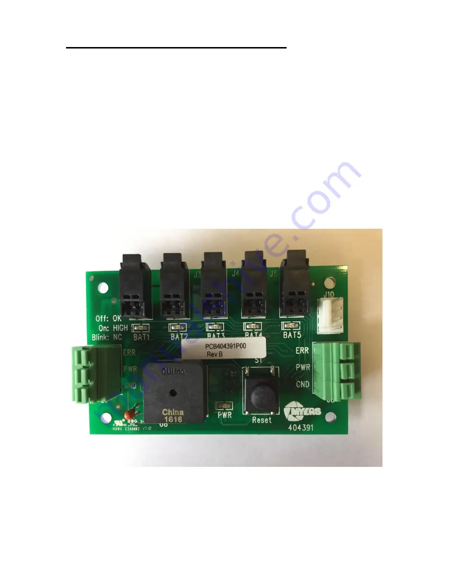
Temperature Sensor PCB Connections:
The Temperature Sensor PCB can be identified by the assembly number
PCB404391XXX. The power is supplied to the connector on the left as well as
the connector on the right labeled ERR, PWR, and GND. The two connectors
support daisy chaining from one temperature sensor circuit board to another*.
*Note
– A maximum of four daisy chained Temperature Sensor PCB’s can be
connected to a single Power Supply/Summary Relay PCB.
Two position insulation displacement connectors, J1-J5, provide the termination
for the battery temperature probes. The temperature probe are NTC type and
have a measurement range from -40°C to 125°C**. The wire length of the
temperature probes can be cut to any length without adversely affecting the
temperature accuracy.
**Note
– Only use Myers Emergency Power Systems supplied temperature
probes (Part# RE-THER2100I).
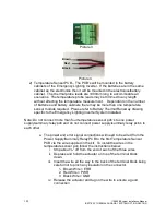
Picture 2
– Temperature Sensor PCB
Summary of Contents for Illuminator Supernova Series
Page 16: ...15 115895B System Installation Manual Figure 5 2 AC Connections for 6 25 k W 7 5 kW systems ...
Page 17: ...16 115895B System Installation Manual Figure 5 3 AC Connections for 10 kW 16 7 kW systems ...
Page 30: ...115895B System Installation Manual PART II OPTIONS MANUALS Section continues on next page ...
Page 95: ...94 115895B System Installation Manual SERIAL TO ETHERNET ADAPTER OPTION SECTION ...
Page 96: ...95 115895B System Installation Manual SERIAL TO ETHERNET ADAPTER OPTION SECTION ...
Page 114: ...113 115895B System Installation Manual DRAWINGS SECTION ...
Page 115: ...114 115895B System Installation Manual DRAWINGS SECTION ...
Page 116: ...115 115895B System Installation Manual DRAWINGS SECTION ...
Page 117: ...116 115895B System Installation Manual DRAWINGS SECTION ...
Page 118: ...117 115895B System Installation Manual DRAWINGS SECTION ...
Page 119: ...118 115895B System Installation Manual DRAWINGS SECTION ...
Page 120: ...119 115895B System Installation Manual DRAWINGS SECTION ...
Page 121: ...120 115895B System Installation Manual DRAWINGS SECTION ...
Page 122: ...121 115895B System Installation Manual DRAWINGS SECTION ...
Page 123: ...122 115895B System Installation Manual DRAWINGS SECTION ...
Page 124: ...123 115895B System Installation Manual DRAWINGS SECTION ...
Page 125: ...124 115895B System Installation Manual DRAWINGS SECTION ...
Page 126: ...125 115895B System Installation Manual DRAWINGS SECTION ...
Page 127: ...126 115895B System Installation Manual DRAWINGS SECTION ...
Page 128: ...127 115895B System Installation Manual DRAWINGS SECTION ...
Page 129: ...128 115895B System Installation Manual DRAWINGS SECTION ...
Page 130: ...129 115895B System Installation Manual DRAWINGS SECTION ...
Page 131: ...130 115895B System Installation Manual Notes ...


