106
115895B System Installation Manual
BATTERY THERMAL RUNAWAY SYSTEM OPTION SECTION
System Schematic:
Figure 1 shows a schematic of the power supply and temperature sensor
PCB and the connections. The schematic shows a two temperature sensor
board system with four temperature probes connected to each monitoring board
but there are many other different possible configurations. Dry contacts are setup
for normally open configuration. Contact rating: 0.5 Amps @ 277VAC maximum.
Figure 1
–System Schematic
SECTION 2
Description of Operation
The Thermal Runaway System monitors each of the battery temperatures
individually and annunciates an alarm if one of two conditions occurs.
1) If any of the connected battery temperature probes measure a
differential rise greater than 40°C between the measured battery
temperature and the ambient temperature as measured from a
temperature sensor on the Temperature Sensor PCB.***
***Note: The Temperature Sensor PCB Modules must be mounted in
proximity to the batteries that are being measured. Never lengthen or
splice the supplied battery temperature probes to move the Temperature
Sensor PCB further from the measured batteries.
2) If any of the connected battery temperature probes measure an
absolute temperature greater than 80°C.
Summary of Contents for Illuminator Supernova Series
Page 16: ...15 115895B System Installation Manual Figure 5 2 AC Connections for 6 25 k W 7 5 kW systems ...
Page 17: ...16 115895B System Installation Manual Figure 5 3 AC Connections for 10 kW 16 7 kW systems ...
Page 30: ...115895B System Installation Manual PART II OPTIONS MANUALS Section continues on next page ...
Page 95: ...94 115895B System Installation Manual SERIAL TO ETHERNET ADAPTER OPTION SECTION ...
Page 96: ...95 115895B System Installation Manual SERIAL TO ETHERNET ADAPTER OPTION SECTION ...
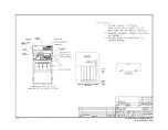
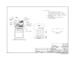
Page 114: ...113 115895B System Installation Manual DRAWINGS SECTION ...
Page 115: ...114 115895B System Installation Manual DRAWINGS SECTION ...
Page 116: ...115 115895B System Installation Manual DRAWINGS SECTION ...
Page 117: ...116 115895B System Installation Manual DRAWINGS SECTION ...
Page 118: ...117 115895B System Installation Manual DRAWINGS SECTION ...
Page 119: ...118 115895B System Installation Manual DRAWINGS SECTION ...
Page 120: ...119 115895B System Installation Manual DRAWINGS SECTION ...
Page 121: ...120 115895B System Installation Manual DRAWINGS SECTION ...
Page 122: ...121 115895B System Installation Manual DRAWINGS SECTION ...
Page 123: ...122 115895B System Installation Manual DRAWINGS SECTION ...
Page 124: ...123 115895B System Installation Manual DRAWINGS SECTION ...
Page 125: ...124 115895B System Installation Manual DRAWINGS SECTION ...
Page 126: ...125 115895B System Installation Manual DRAWINGS SECTION ...
Page 127: ...126 115895B System Installation Manual DRAWINGS SECTION ...
Page 128: ...127 115895B System Installation Manual DRAWINGS SECTION ...
Page 129: ...128 115895B System Installation Manual DRAWINGS SECTION ...
Page 130: ...129 115895B System Installation Manual DRAWINGS SECTION ...
Page 131: ...130 115895B System Installation Manual Notes ...


