107
115895B System Installation Manual
BATTERY THERMAL RUNAWAY SYSTEM OPTION SECTION
If a battery is in a thermal runaway condition there are four indications that will
result. The four conditions will remain in a latched state until the reset button is
depressed for a few seconds and then released.
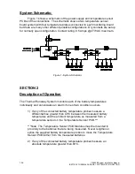
1) The summary alarm contact will be activated.
2) The audible summary alarm will be activated on the temperature
sensor pcb with the battery that is in a thermal runaway condition.
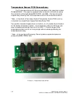
3) The LED below the particular battery temperature probe connector on
the temperature sensor pcb will be illuminated.
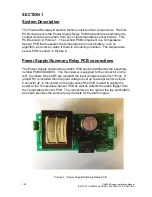
4) The Battery Overtemp LED on the power supply/summary relay pcb
will be illuminated.
LED Definitions
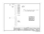
1) Power Supply/Summary Relay PCB (PCB404394XXX)
a. Battery Overtemp LED
– Illuminated when a battery is experiencing
thermal runaway condition on one or more of the batteries on the
connected Temperature Sensor PCB.
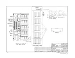
2) Temperature Sensor PCB (PCB404391XXX)
a. PWR LED
– Illuminated when the +5V supply is present on the
temperature sensor pcb.
b. BAT1-BAT5
– There are three states of the LED for each of the
battery temperature probes.
i. LED OFF
– Temperature probe connected and in tolerance.
ii. LED ON
– Connected battery is in a thermal runaway
condition.
iii. LED Flash
– Temperature probe not connected****.
****Note: If a temperature probe is not connected all other probe channels will
operate normally. The probe that is not connected will be ignored.
Summary of Contents for Illuminator Supernova Series
Page 16: ...15 115895B System Installation Manual Figure 5 2 AC Connections for 6 25 k W 7 5 kW systems ...
Page 17: ...16 115895B System Installation Manual Figure 5 3 AC Connections for 10 kW 16 7 kW systems ...
Page 30: ...115895B System Installation Manual PART II OPTIONS MANUALS Section continues on next page ...
Page 95: ...94 115895B System Installation Manual SERIAL TO ETHERNET ADAPTER OPTION SECTION ...
Page 96: ...95 115895B System Installation Manual SERIAL TO ETHERNET ADAPTER OPTION SECTION ...
Page 114: ...113 115895B System Installation Manual DRAWINGS SECTION ...
Page 115: ...114 115895B System Installation Manual DRAWINGS SECTION ...
Page 116: ...115 115895B System Installation Manual DRAWINGS SECTION ...
Page 117: ...116 115895B System Installation Manual DRAWINGS SECTION ...
Page 118: ...117 115895B System Installation Manual DRAWINGS SECTION ...
Page 119: ...118 115895B System Installation Manual DRAWINGS SECTION ...
Page 120: ...119 115895B System Installation Manual DRAWINGS SECTION ...
Page 121: ...120 115895B System Installation Manual DRAWINGS SECTION ...
Page 122: ...121 115895B System Installation Manual DRAWINGS SECTION ...
Page 123: ...122 115895B System Installation Manual DRAWINGS SECTION ...
Page 124: ...123 115895B System Installation Manual DRAWINGS SECTION ...
Page 125: ...124 115895B System Installation Manual DRAWINGS SECTION ...
Page 126: ...125 115895B System Installation Manual DRAWINGS SECTION ...
Page 127: ...126 115895B System Installation Manual DRAWINGS SECTION ...
Page 128: ...127 115895B System Installation Manual DRAWINGS SECTION ...
Page 129: ...128 115895B System Installation Manual DRAWINGS SECTION ...
Page 130: ...129 115895B System Installation Manual DRAWINGS SECTION ...
Page 131: ...130 115895B System Installation Manual Notes ...

