19
115895B System Installation Manual
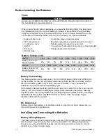
Before Installing the Batteries
Tools
CAUTION
Always use insulated tools when you work with batteries. Always torque connections to
the manufacturer’s recommendations.
When you work with system batteries, you need the following tools. The tools must
be insulated so they do not short battery terminals to the cabinet. Wear the safety
equipment required by local code whenever the doors are open and whenever you
are working on batteries. Other tools may be necessary for optional batteries.
•
Digital volt-ohm meter
•
Conductive grease or petroleum jelly
•
7
/16” socket wrench
•
Brush (to apply grease or petroleum jelly to terminals)
•
3” extension socket
•
Safety equipment required by local codes
•
Ratchet
•
Torque wrench calibrated in inch-pounds or Newton-meters
•
Wire brush
•
Safety glasses with side shields
•
Electrical tape
Battery Voltage (vdc)
Models
1.75k
2.5k
3.75k
5.0k
6.25k
7.5k
10.0k 12.5k 16.7k
Battery Volts for 90
Minute Systems
48v
48v
72v
96v
120v
144v
144v
180v
240v
Models
1.31k 1.88k 2.81k 3.75k 4.69k 5.63k
7.5k
9.38k 12.5k
Battery Volts for 120
Minute Systems
48v
48v
72v
96v
120v
144v
144v
180v
240v
Battery Cable Sizing
The battery cable or wire used varies. For the 100 AH battery (BAT-CG12105X) the
size is 6 AWG, for the 150 AH battery (BAT-CG12150X) the size is 4 AWG, and for
the 180 AH battery (BAT-CG12180X), the size is 2 AWG. This is because the
batteries string current varies with battery type.
If the battery cabinets must be more than two feet (0.6 meters) from the main inverter
cabinet, you may need to install larger battery cables between the battery cabinets
and the system. Using long cable runs and larger diameter cables require a modified
installation of the system; call SERVICE if you did not order the longer, larger-
diameter cable with the system.
DC Disconnect
Systems have a Main Battery Circuit Breaker inside the cabinet; this circuit breaker lets you
remove DC power from the batteries.
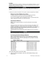
Installing and Connecting the Batteries
Battery Wiring Diagram
The battery interconnect wiring diagrams are in the rear of this manual and you should have
also received a copy with your system in the documentation. This battery-wiring diagram
shows how you should install the batteries, make terminal, and fuse connections. Use the
diagram as you follow the steps below.
Summary of Contents for Illuminator Supernova Series
Page 16: ...15 115895B System Installation Manual Figure 5 2 AC Connections for 6 25 k W 7 5 kW systems ...
Page 17: ...16 115895B System Installation Manual Figure 5 3 AC Connections for 10 kW 16 7 kW systems ...
Page 30: ...115895B System Installation Manual PART II OPTIONS MANUALS Section continues on next page ...
Page 95: ...94 115895B System Installation Manual SERIAL TO ETHERNET ADAPTER OPTION SECTION ...
Page 96: ...95 115895B System Installation Manual SERIAL TO ETHERNET ADAPTER OPTION SECTION ...
Page 114: ...113 115895B System Installation Manual DRAWINGS SECTION ...
Page 115: ...114 115895B System Installation Manual DRAWINGS SECTION ...
Page 116: ...115 115895B System Installation Manual DRAWINGS SECTION ...
Page 117: ...116 115895B System Installation Manual DRAWINGS SECTION ...
Page 118: ...117 115895B System Installation Manual DRAWINGS SECTION ...
Page 119: ...118 115895B System Installation Manual DRAWINGS SECTION ...
Page 120: ...119 115895B System Installation Manual DRAWINGS SECTION ...
Page 121: ...120 115895B System Installation Manual DRAWINGS SECTION ...
Page 122: ...121 115895B System Installation Manual DRAWINGS SECTION ...
Page 123: ...122 115895B System Installation Manual DRAWINGS SECTION ...
Page 124: ...123 115895B System Installation Manual DRAWINGS SECTION ...
Page 125: ...124 115895B System Installation Manual DRAWINGS SECTION ...
Page 126: ...125 115895B System Installation Manual DRAWINGS SECTION ...
Page 127: ...126 115895B System Installation Manual DRAWINGS SECTION ...
Page 128: ...127 115895B System Installation Manual DRAWINGS SECTION ...
Page 129: ...128 115895B System Installation Manual DRAWINGS SECTION ...
Page 130: ...129 115895B System Installation Manual DRAWINGS SECTION ...
Page 131: ...130 115895B System Installation Manual Notes ...


