20
115895B System Installation Manual
Location
The system batteries belong inside the unit. Before you start installing the batteries, you must
install the system in its permanent location. If you have not already do
ne this, see “Location
Guidel
ines” on page 9 to choose a location.
CAUTION
To prevent damage to your equipment, do not move the system after the batteries are
installed.
To make sure a location is acceptable for the system, review the requirements in Chapter 3.
Electronics Cabinet Battery Connections
The battery cables are connected to the battery circuit breaker at the factory.
All of the single-phase systems have only one series battery string.
Do not connect any battery cables to the batteries at this time. Use the battery-wiring
diagram shipped with the system as you follow these steps.
Arranging the Batteries
NOTE As you arrange the batteries, you must be wearing the required safety
equipment.
Arrange the batteries in the cabinet only as shown in the battery-wiring diagram. This
arrangement is designed to maximize airflow around the batteries. The cabinets are
designed so that battery cases should never touch. Air should be free to circulate. Clean
the entire surface of all battery terminals with the wire brush before you install the
batteries to create good contact points.
Load the batteries into the system. Starting with the bottom shelf, load one shelf at a
time.
CAUTION
Never install the batteries in an airtight enclosure.
Connecting the Cables Between Batteries
When you make battery terminal connections, use the torque wrench to tighten the
battery terminal connections securely. You can find out what torque value to use by
finding the battery number on the front of the battery. Then, use Table 6.1 to find the
torque value for that battery.
Table 6.1 Battery Torque
Battery Type
Torque
BAT-CG12105E
Torque to 100 in lbs. (11.3 Nm)
BAT-CG12105G
Torque to 100 in lbs. (11.3 Nm)
BAT-CG12105H
Torque to 110 in lbs. (12.4 Nm)
BAT-CG12105I
Torque to 120 in lbs. (13.6 Nm)
BAT-CG12150B
Torque to 120 in lbs. (13.6 Nm)
BAT-CG12150C
Torque to 100 in lbs. (11.3 Nm)
BAT-CG12150D
Torque to 100 in lbs. (11.3 Nm)
BAT-CG12180
Torque to 100 in lbs. (11.3 Nm)
BAT-CG12180A
Torque to 120 in lbs. (13.6 Nm)
Now, follow these steps to connect the cables:
1.
Using the battery-wiring diagram, determine which batteries belong to each
battery string.
Summary of Contents for Illuminator Supernova Series
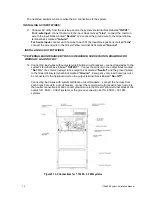
Page 16: ...15 115895B System Installation Manual Figure 5 2 AC Connections for 6 25 k W 7 5 kW systems ...
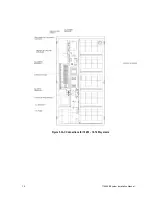
Page 17: ...16 115895B System Installation Manual Figure 5 3 AC Connections for 10 kW 16 7 kW systems ...
Page 30: ...115895B System Installation Manual PART II OPTIONS MANUALS Section continues on next page ...
Page 95: ...94 115895B System Installation Manual SERIAL TO ETHERNET ADAPTER OPTION SECTION ...
Page 96: ...95 115895B System Installation Manual SERIAL TO ETHERNET ADAPTER OPTION SECTION ...
Page 114: ...113 115895B System Installation Manual DRAWINGS SECTION ...
Page 115: ...114 115895B System Installation Manual DRAWINGS SECTION ...
Page 116: ...115 115895B System Installation Manual DRAWINGS SECTION ...
Page 117: ...116 115895B System Installation Manual DRAWINGS SECTION ...
Page 118: ...117 115895B System Installation Manual DRAWINGS SECTION ...
Page 119: ...118 115895B System Installation Manual DRAWINGS SECTION ...
Page 120: ...119 115895B System Installation Manual DRAWINGS SECTION ...
Page 121: ...120 115895B System Installation Manual DRAWINGS SECTION ...
Page 122: ...121 115895B System Installation Manual DRAWINGS SECTION ...
Page 123: ...122 115895B System Installation Manual DRAWINGS SECTION ...
Page 124: ...123 115895B System Installation Manual DRAWINGS SECTION ...
Page 125: ...124 115895B System Installation Manual DRAWINGS SECTION ...
Page 126: ...125 115895B System Installation Manual DRAWINGS SECTION ...
Page 127: ...126 115895B System Installation Manual DRAWINGS SECTION ...
Page 128: ...127 115895B System Installation Manual DRAWINGS SECTION ...
Page 129: ...128 115895B System Installation Manual DRAWINGS SECTION ...
Page 130: ...129 115895B System Installation Manual DRAWINGS SECTION ...
Page 131: ...130 115895B System Installation Manual Notes ...

