115895B System Installation Manual
CHAPTER 7
T
URNING ON THE
S
YSTEM AND
S
ETTING
P
ARAMETERS
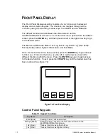
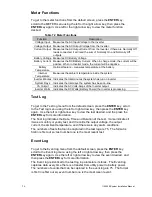
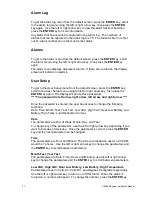
Several parameters in the system software determine when and how your system
conducts the automatic monthly and annual tests. Refe
r to “User Setup” in the “Front
Panel Display” chapter of the system user’s Guide for a description of each test.
Starting the Unit
Before you can set the parameters, you must start the system.
WARNING
Verify that the system AC Input Circuit Breaker and Installation Switch are off.
1. Turn on the AC input at the building service panel; ensure that the systems
input breaker (CB1) is off.
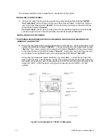
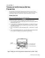
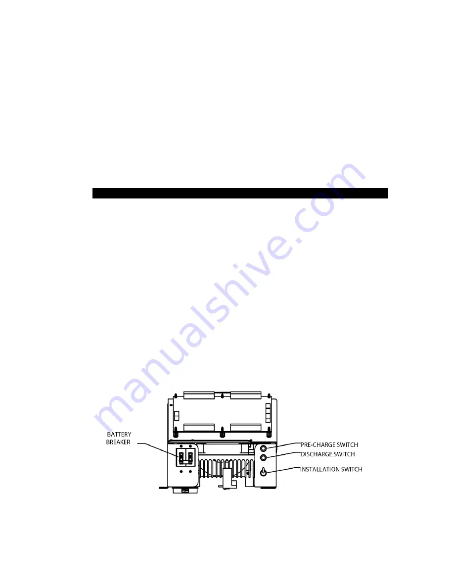
2. Locate the DC Pre-charge Switch (S2), see figure 7.1 or figure 7.2 or figure
7.3; press it for five seconds; then, install the main battery fuse (F1) inside
the electronics cabinet.
3. Turn on the System AC input circuit breaker (CB1). (See figure 5.1 or figure
5.2)
4. Turn on the Installation Switch (S1). Leave the loads (protected equipment)
off. Unit will run on batteries, then transfer to normal mode.
Figure 7.1 Battery Fuse, DC Pre-charge Switch & Installation Switch (1.75 kW
–
5.0 kW)
Summary of Contents for Illuminator Supernova Series
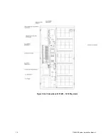
Page 16: ...15 115895B System Installation Manual Figure 5 2 AC Connections for 6 25 k W 7 5 kW systems ...
Page 17: ...16 115895B System Installation Manual Figure 5 3 AC Connections for 10 kW 16 7 kW systems ...
Page 30: ...115895B System Installation Manual PART II OPTIONS MANUALS Section continues on next page ...
Page 95: ...94 115895B System Installation Manual SERIAL TO ETHERNET ADAPTER OPTION SECTION ...
Page 96: ...95 115895B System Installation Manual SERIAL TO ETHERNET ADAPTER OPTION SECTION ...
Page 114: ...113 115895B System Installation Manual DRAWINGS SECTION ...
Page 115: ...114 115895B System Installation Manual DRAWINGS SECTION ...
Page 116: ...115 115895B System Installation Manual DRAWINGS SECTION ...
Page 117: ...116 115895B System Installation Manual DRAWINGS SECTION ...
Page 118: ...117 115895B System Installation Manual DRAWINGS SECTION ...
Page 119: ...118 115895B System Installation Manual DRAWINGS SECTION ...
Page 120: ...119 115895B System Installation Manual DRAWINGS SECTION ...
Page 121: ...120 115895B System Installation Manual DRAWINGS SECTION ...
Page 122: ...121 115895B System Installation Manual DRAWINGS SECTION ...
Page 123: ...122 115895B System Installation Manual DRAWINGS SECTION ...
Page 124: ...123 115895B System Installation Manual DRAWINGS SECTION ...
Page 125: ...124 115895B System Installation Manual DRAWINGS SECTION ...
Page 126: ...125 115895B System Installation Manual DRAWINGS SECTION ...
Page 127: ...126 115895B System Installation Manual DRAWINGS SECTION ...
Page 128: ...127 115895B System Installation Manual DRAWINGS SECTION ...
Page 129: ...128 115895B System Installation Manual DRAWINGS SECTION ...
Page 130: ...129 115895B System Installation Manual DRAWINGS SECTION ...
Page 131: ...130 115895B System Installation Manual Notes ...

