38
115895B System Installation Manual
BACNET IP & SNMP COMMUNICATION OPTION SECTION
SECTION 1
BACNET MS/TP Communication Board
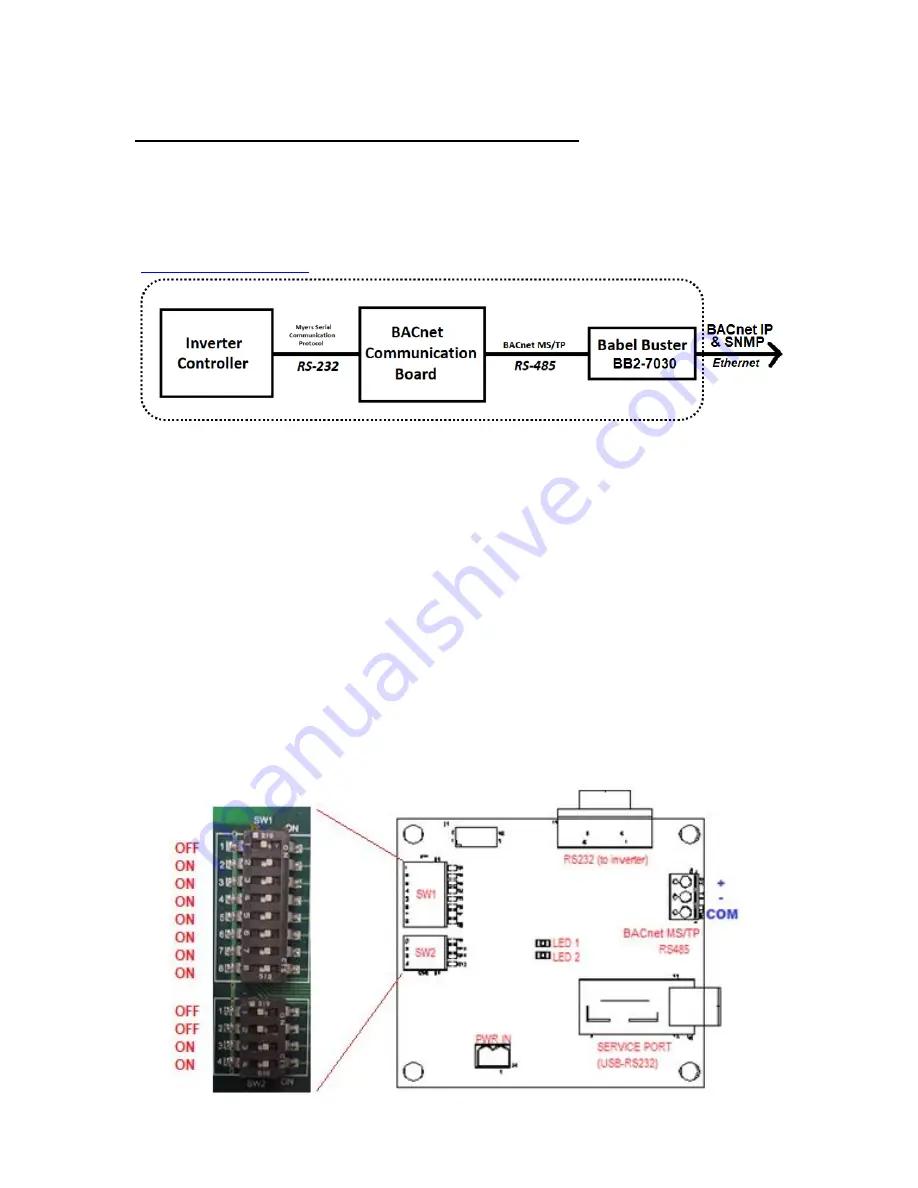
BACnet IP and SNMP communication from the single-phase Illuminator
Supernova Emergency Lighting Central Inverter is achieved via a standard Myers EPS
BACnet MS/TP communication board
– which converts the RS-232 communication with
the inverter controller into the BACnet MS/TP protocol
– and a Babel Buster BB2-7030
BACnet MS/TP to BACnet IP Gateway and Router, made by Control Solutions Inc.
(
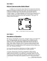
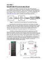
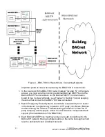
). Figure 1 describes the data flow at a high level.
Figure 1
– Data Flow to Achieve BACnet IP and SNMP Integration
Everything inside the dashed box (including the Control Solutions Inc. Babel
Buster BB2-7030) is pre-wired, pre-programmed and pre-configured by Myers EPS, and
is internally mounted and powered inside the inverter cabinet (and will remain powered
when the utility A/C input goes down and the inverter switches to battery power). The
integrator may integrate directly to the Ethernet link on the BB2-7030. The below
information on the BACnet Communication Board is for your information only.
The BACnet Communication Option Board for the single-phase Illuminator
Supernova Emergency Lighting Central Inverter has two internal connections; the
RS232 communication bus to the inverter controller, and the input power that powers the
board. There are two external connections, a RS485 output connector that is the BACnet
MS/TP link, and a USB connection that is a serial computer interface into the RS232
communication bus to the inverter controller. For detailed operation on the protocol and
commands for the computer interface see manual 114063 RS-232 Communications.
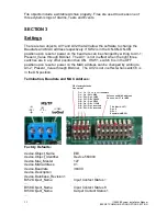
There are also two DIP switches that setup the BACnet MS/TP communication settings.
These should not be changed.
Figure 2 shows a diagram of the BACnet
Communication Board and required DIP settings.
Summary of Contents for Illuminator Supernova Series
Page 16: ...15 115895B System Installation Manual Figure 5 2 AC Connections for 6 25 k W 7 5 kW systems ...
Page 17: ...16 115895B System Installation Manual Figure 5 3 AC Connections for 10 kW 16 7 kW systems ...
Page 30: ...115895B System Installation Manual PART II OPTIONS MANUALS Section continues on next page ...
Page 95: ...94 115895B System Installation Manual SERIAL TO ETHERNET ADAPTER OPTION SECTION ...
Page 96: ...95 115895B System Installation Manual SERIAL TO ETHERNET ADAPTER OPTION SECTION ...
Page 114: ...113 115895B System Installation Manual DRAWINGS SECTION ...
Page 115: ...114 115895B System Installation Manual DRAWINGS SECTION ...
Page 116: ...115 115895B System Installation Manual DRAWINGS SECTION ...
Page 117: ...116 115895B System Installation Manual DRAWINGS SECTION ...
Page 118: ...117 115895B System Installation Manual DRAWINGS SECTION ...
Page 119: ...118 115895B System Installation Manual DRAWINGS SECTION ...
Page 120: ...119 115895B System Installation Manual DRAWINGS SECTION ...
Page 121: ...120 115895B System Installation Manual DRAWINGS SECTION ...
Page 122: ...121 115895B System Installation Manual DRAWINGS SECTION ...
Page 123: ...122 115895B System Installation Manual DRAWINGS SECTION ...
Page 124: ...123 115895B System Installation Manual DRAWINGS SECTION ...
Page 125: ...124 115895B System Installation Manual DRAWINGS SECTION ...
Page 126: ...125 115895B System Installation Manual DRAWINGS SECTION ...
Page 127: ...126 115895B System Installation Manual DRAWINGS SECTION ...
Page 128: ...127 115895B System Installation Manual DRAWINGS SECTION ...
Page 129: ...128 115895B System Installation Manual DRAWINGS SECTION ...
Page 130: ...129 115895B System Installation Manual DRAWINGS SECTION ...
Page 131: ...130 115895B System Installation Manual Notes ...


