44
115895B System Installation Manual
BACNET IP & SNMP COMMUNICATION OPTION SECTION
Setting Up BACnet IP (Including Device Instance)
Once the IP address is correctly set, the BACnet IP should immediately be
working using the IP address you set, Device Instance number 20800, Port
47808, and the BACnet objects described above in Section 4. If these settings
are OK, you
’re good to go.
If you need to change the Device Instance number (
which must be
globally unique on the BACnet network
) or Port Number, you can do so on the
following page:
“System Setup” >> “Setup” >> “BACnet IP Port” . Make the
required changes, click the
“Save” button, and then refer to the “Saving and
Activating Your Changes
” subsection below to make your changes permanent
(otherwise, they may be lost if the inverter loses power for long enough for
the entire battery to deplete, or if maintenance is performed on the
inverter)
.
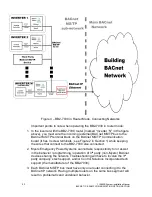
By default, the BB2-7030 acts as a BACnet MS/TP to BACnet IP gateway
(proxy) for one device (the single Myers EPS inverter system). In the unlikely
case that you wish to configure it to be a BACnet router, see the section below
on Gateway vs Router.
Setting Up the SNMP Agent
Once the IP address is correctly set, the SNMP Agent (server) should
immediately be working using the IP address you set,
“public” as the community,
and
“Get” operations on the SNMP OIDs described in Section 4 above (after the
first
“Get”, you may use “Get Next” as well, or walk the entire MIB). If these
settings are OK, you
’re good to go.
The BB2-7030 supports SNMP v1 and v2c. Note that SNMP v3 is
not
supported.
Setting Up SNMP Traps
The BB2-7030 can use SNMP
’s “trap” mechanism to generate
notifications (and send them to one or more trap receiving PCs/devices) when a
programmed condition occurs. By default, no traps are programmed. You are
only able to program one trap per object (see object list in Section 4).
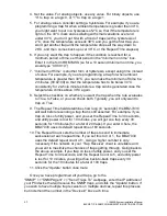
To program traps, go to the
“SNMP” >> “SNMP Agent” >> “Traps”
webpage. You must follow the below instructions for each trap you wish to
program:
1. Enter the last number (number after the last
‘.’) of the OID of the object
you wish to program a trap for (see object list in Section 4).
2. Click the
‘Update’ button.
3. Select the rule from the dropdown menu. Allowed rules for analog objects
are
“greater than”, “greater or equal”, “less than”, “less or equal”, “equal
to
” and “not equal to”. For binary objects, you only need the “equal” rule.
Summary of Contents for Illuminator Supernova Series
Page 16: ...15 115895B System Installation Manual Figure 5 2 AC Connections for 6 25 k W 7 5 kW systems ...
Page 17: ...16 115895B System Installation Manual Figure 5 3 AC Connections for 10 kW 16 7 kW systems ...
Page 30: ...115895B System Installation Manual PART II OPTIONS MANUALS Section continues on next page ...
Page 95: ...94 115895B System Installation Manual SERIAL TO ETHERNET ADAPTER OPTION SECTION ...
Page 96: ...95 115895B System Installation Manual SERIAL TO ETHERNET ADAPTER OPTION SECTION ...
Page 114: ...113 115895B System Installation Manual DRAWINGS SECTION ...
Page 115: ...114 115895B System Installation Manual DRAWINGS SECTION ...
Page 116: ...115 115895B System Installation Manual DRAWINGS SECTION ...
Page 117: ...116 115895B System Installation Manual DRAWINGS SECTION ...
Page 118: ...117 115895B System Installation Manual DRAWINGS SECTION ...
Page 119: ...118 115895B System Installation Manual DRAWINGS SECTION ...
Page 120: ...119 115895B System Installation Manual DRAWINGS SECTION ...
Page 121: ...120 115895B System Installation Manual DRAWINGS SECTION ...
Page 122: ...121 115895B System Installation Manual DRAWINGS SECTION ...
Page 123: ...122 115895B System Installation Manual DRAWINGS SECTION ...
Page 124: ...123 115895B System Installation Manual DRAWINGS SECTION ...
Page 125: ...124 115895B System Installation Manual DRAWINGS SECTION ...
Page 126: ...125 115895B System Installation Manual DRAWINGS SECTION ...
Page 127: ...126 115895B System Installation Manual DRAWINGS SECTION ...
Page 128: ...127 115895B System Installation Manual DRAWINGS SECTION ...
Page 129: ...128 115895B System Installation Manual DRAWINGS SECTION ...
Page 130: ...129 115895B System Installation Manual DRAWINGS SECTION ...
Page 131: ...130 115895B System Installation Manual Notes ...

