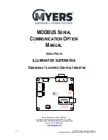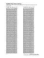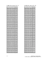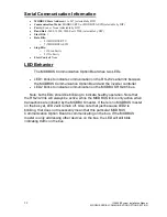
45
115895B System Installation Manual
BACNET IP & SNMP COMMUNICATION OPTION SECTION
4. Set the value. For analog objects, use any value. For binary objects, use
“0” to trap on a logic 0, or “1” to trap on a logic 1.
5. For analog values, consider setting a hysteresis. For example, if you are
programming a trap for when ambient temperature is greater than 30°C,
you might want to put in a hysteresis of 2°C so that if the temperature is
right on the 30°C mark and oscillating with small variations over and
under 30°C, you don
’t get hit with a flood of traps (with a hysteresis of
2°C, once the temperature exceeds 30°C and you get the first trap, you
won
’t get another trap until the temperature drops all the way down to
28°C, and then comes back up over 30°C, or the Repeat Time elapses)
6. If you only want the trap to happen if the condition is reached for a
minimum period of time, set that period in the
“minimum on time” box.
Enter it in the form HH:MM:SS (so for a 10 second minimum on time, you
would type
“00:00:10”)
7.
“minimum off time” is another form of hysteresis, except using time instead
of value. For example, if you are programming a trap for when ambient
temperature is greater than 30°C, you can make the minimum off time be
2 minutes (00:02:00) so that the temperature has to be below 30°C
consistently for 2 whole minutes before a trap can be generated once the
temperature climbs above 30°C again.
8. Select the checkbox on whether you want the trap when the rule evaluates
to True, to False, or you can check both. Typically, you will only want to
trap on True.
9. The Repeat Time field determines how long (in
‘seconds’) the BB2-7030
will wait before resending a trap that is still asserted. For example, if you
trap on loss of utility power, and you set the Repeat Time to 30 seconds,
and utility power is lost for 10 minutes, you will get one trap every 30
seconds for 10 minutes (for a total of 20 traps). If you enter 0 here, the
BB2-7030 uses its default repeat time of 60 seconds.
10. The Repeat Count sets the number of traps to send in immediate
succession at each repeat time. If you set this to 0 or 1, the BB2-7030
uses the default repeat count of 1. Using a higher number is only
necessary if the network or your
‘Trap Receiver’ client is unreliable and
you want to maximize the chances of traps getting through. Going back to
the above example, if you trap on loss of utility power, and you set the
Repeat Time to 30 seconds, and the Repeat Count to 5, and utility power
is lost for 10 minutes, you will get five back-to-back traps every 30
seconds for the 10 minutes for a total of 100 traps.
11. Click the
“Update” button once more.
Once you have programmed all your traps, go to the
“SNMP” >> “SNMP Agent” >> “Send Traps To” webpage, enter the IP address of
your PC/device that will receive the SNMP traps, and click the
“Update” button. If
you wish to have multiple trap receivers on multiple devices, repeat this process
but increment the number in the
“Device #” box each time.
Summary of Contents for Illuminator Supernova Series
Page 16: ...15 115895B System Installation Manual Figure 5 2 AC Connections for 6 25 k W 7 5 kW systems ...
Page 17: ...16 115895B System Installation Manual Figure 5 3 AC Connections for 10 kW 16 7 kW systems ...
Page 30: ...115895B System Installation Manual PART II OPTIONS MANUALS Section continues on next page ...
Page 95: ...94 115895B System Installation Manual SERIAL TO ETHERNET ADAPTER OPTION SECTION ...
Page 96: ...95 115895B System Installation Manual SERIAL TO ETHERNET ADAPTER OPTION SECTION ...
Page 114: ...113 115895B System Installation Manual DRAWINGS SECTION ...
Page 115: ...114 115895B System Installation Manual DRAWINGS SECTION ...
Page 116: ...115 115895B System Installation Manual DRAWINGS SECTION ...
Page 117: ...116 115895B System Installation Manual DRAWINGS SECTION ...
Page 118: ...117 115895B System Installation Manual DRAWINGS SECTION ...
Page 119: ...118 115895B System Installation Manual DRAWINGS SECTION ...
Page 120: ...119 115895B System Installation Manual DRAWINGS SECTION ...
Page 121: ...120 115895B System Installation Manual DRAWINGS SECTION ...
Page 122: ...121 115895B System Installation Manual DRAWINGS SECTION ...
Page 123: ...122 115895B System Installation Manual DRAWINGS SECTION ...
Page 124: ...123 115895B System Installation Manual DRAWINGS SECTION ...
Page 125: ...124 115895B System Installation Manual DRAWINGS SECTION ...
Page 126: ...125 115895B System Installation Manual DRAWINGS SECTION ...
Page 127: ...126 115895B System Installation Manual DRAWINGS SECTION ...
Page 128: ...127 115895B System Installation Manual DRAWINGS SECTION ...
Page 129: ...128 115895B System Installation Manual DRAWINGS SECTION ...
Page 130: ...129 115895B System Installation Manual DRAWINGS SECTION ...
Page 131: ...130 115895B System Installation Manual Notes ...

