48
115895B System Installation Manual
BACNET IP & SNMP COMMUNICATION OPTION SECTION
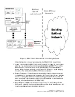
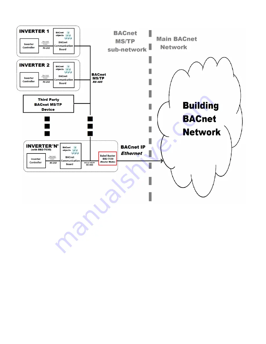
Figure 4
– BB2-7030 in Router Mode, Connecting Networks
Important points to note when operating the BB2-7030 in router mode:
1. In the inverter with the BB2-7030 router (marked
“Inverter ‘N’” in the figure
above), you must wire the incoming (external) BACnet MS/TP bus to the
BACnet MS/TP terminal block on the BACnet MS/TP Communication
board (it has 3 screw terminals ; see Figure 2 in Section 1) while keeping
the wires that connect to the BB2-7030 also connected.
2. Myers Emergency Power Systems cannot take responsibility for or assist
in the behavior / programming / operation of 3
rd
party (non-Myers) BACnet
devices sharing the network. Troubleshooting will have to involve the 3
rd
party company
’s tech support, and/or Control Solutions Incorporated tech
support (the manufacturer of the BB2-7030).
3. Each BACnet MS/TP bus must have only one router connecting it to the
BACnet IP network. Having multiple routers on the same bus segment will
result in problematic and undefined behavior.
Summary of Contents for Illuminator Supernova Series
Page 16: ...15 115895B System Installation Manual Figure 5 2 AC Connections for 6 25 k W 7 5 kW systems ...
Page 17: ...16 115895B System Installation Manual Figure 5 3 AC Connections for 10 kW 16 7 kW systems ...
Page 30: ...115895B System Installation Manual PART II OPTIONS MANUALS Section continues on next page ...
Page 95: ...94 115895B System Installation Manual SERIAL TO ETHERNET ADAPTER OPTION SECTION ...
Page 96: ...95 115895B System Installation Manual SERIAL TO ETHERNET ADAPTER OPTION SECTION ...
Page 114: ...113 115895B System Installation Manual DRAWINGS SECTION ...
Page 115: ...114 115895B System Installation Manual DRAWINGS SECTION ...
Page 116: ...115 115895B System Installation Manual DRAWINGS SECTION ...
Page 117: ...116 115895B System Installation Manual DRAWINGS SECTION ...
Page 118: ...117 115895B System Installation Manual DRAWINGS SECTION ...
Page 119: ...118 115895B System Installation Manual DRAWINGS SECTION ...
Page 120: ...119 115895B System Installation Manual DRAWINGS SECTION ...
Page 121: ...120 115895B System Installation Manual DRAWINGS SECTION ...
Page 122: ...121 115895B System Installation Manual DRAWINGS SECTION ...
Page 123: ...122 115895B System Installation Manual DRAWINGS SECTION ...
Page 124: ...123 115895B System Installation Manual DRAWINGS SECTION ...
Page 125: ...124 115895B System Installation Manual DRAWINGS SECTION ...
Page 126: ...125 115895B System Installation Manual DRAWINGS SECTION ...
Page 127: ...126 115895B System Installation Manual DRAWINGS SECTION ...
Page 128: ...127 115895B System Installation Manual DRAWINGS SECTION ...
Page 129: ...128 115895B System Installation Manual DRAWINGS SECTION ...
Page 130: ...129 115895B System Installation Manual DRAWINGS SECTION ...
Page 131: ...130 115895B System Installation Manual Notes ...


