50
115895B System Installation Manual
BACNET IP & SNMP COMMUNICATION OPTION SECTION
•
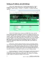
Enter the allocated network numbers for the BACnet IP Network (on the
Ethernet side of this BB2-7030), and for the MS/TP Network (on the
MS/TP RS-485 side of this BB2-7030). See the section below marked
“On Network Numbers” for more detailed information.
•
Enter the hop counts for the BACnet IP and MS/TP networks. See the
section below marked
“On Hop Counts” for more detailed information.
•
Optionally, enter names for each network in the
“Network Info” text boxes.
This is optional, and purely informational. These names will only live within
this BB2-7030 ; they are not global to the network.
•
Finally, click the
“Save” button to temporarily save your changes.
•
To permanently save your changes, refer to the section above titled
“Saving and Activating Your Changes”.
On Network Numbers
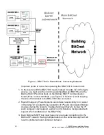
In a large BACnet network that is comprised of multiple smaller sub-
networks with BACnet routers in between, each sub-network in the system must
be assigned a globally unique network number. All routers on the
‘edges’ of that
sub-network must be configured with the same network number for that sub-
network.
If your network only consists of a single MS/TP sub-network and a single
IP network (with a single BB2-7030 in between), then you can assign any two
arbitrary numbers to each sub-network in the BB2-7030
“Network Info”
configuration page.
On Hop Counts
In a large BACnet network that is comprised of multiple smaller sub-
networks with routers in between, each time a message has to cross from one
sub-network to another (through a BACnet router), it is considered a
‘hop’.
Please count the maximum number of hops from any device to any other
device on the network, add 1 or 2 to this number as a small buffer, and use this
number as the Hop Count on the BB2-7030
“Network Info” configuration page.
If your network only consists of a single MS/TP sub-network and a single
IP network (with a single BB2-7030 in between), then you should set the Hop
Count to 2.
Parsing File Records (Alarm, Event and Test Logs)
This section will describe the information contained in Alarm, Event and
Test log files, and how to parse them. These files can only be accessed when the
BB2-7030 is operating in Router Mode. They are accessed as standard BACnet
File Input objects.
Summary of Contents for Illuminator Supernova Series
Page 16: ...15 115895B System Installation Manual Figure 5 2 AC Connections for 6 25 k W 7 5 kW systems ...
Page 17: ...16 115895B System Installation Manual Figure 5 3 AC Connections for 10 kW 16 7 kW systems ...
Page 30: ...115895B System Installation Manual PART II OPTIONS MANUALS Section continues on next page ...
Page 95: ...94 115895B System Installation Manual SERIAL TO ETHERNET ADAPTER OPTION SECTION ...
Page 96: ...95 115895B System Installation Manual SERIAL TO ETHERNET ADAPTER OPTION SECTION ...
Page 114: ...113 115895B System Installation Manual DRAWINGS SECTION ...
Page 115: ...114 115895B System Installation Manual DRAWINGS SECTION ...
Page 116: ...115 115895B System Installation Manual DRAWINGS SECTION ...
Page 117: ...116 115895B System Installation Manual DRAWINGS SECTION ...
Page 118: ...117 115895B System Installation Manual DRAWINGS SECTION ...
Page 119: ...118 115895B System Installation Manual DRAWINGS SECTION ...
Page 120: ...119 115895B System Installation Manual DRAWINGS SECTION ...
Page 121: ...120 115895B System Installation Manual DRAWINGS SECTION ...
Page 122: ...121 115895B System Installation Manual DRAWINGS SECTION ...
Page 123: ...122 115895B System Installation Manual DRAWINGS SECTION ...
Page 124: ...123 115895B System Installation Manual DRAWINGS SECTION ...
Page 125: ...124 115895B System Installation Manual DRAWINGS SECTION ...
Page 126: ...125 115895B System Installation Manual DRAWINGS SECTION ...
Page 127: ...126 115895B System Installation Manual DRAWINGS SECTION ...
Page 128: ...127 115895B System Installation Manual DRAWINGS SECTION ...
Page 129: ...128 115895B System Installation Manual DRAWINGS SECTION ...
Page 130: ...129 115895B System Installation Manual DRAWINGS SECTION ...
Page 131: ...130 115895B System Installation Manual Notes ...

