51
115895B System Installation Manual
BACNET IP & SNMP COMMUNICATION OPTION SECTION
Alarm Logs
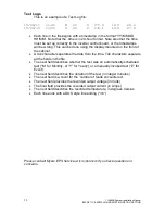
This is an example of an Alarm Log file:
19/08/21 09:31
INVERTER FAULT
19/08/25 22:14
LOW VAC
•
Each line in the file begins with a timestamp in the format
“YY/MM/DD
HH:MM”. Note that the time is in 24-hour format. Note also that the time
must be set up correctly in the inverter control board, or the timestamps
will be wrong. This can be done using the display mounted on the front of
the cabinet.
•
A tab character separates the date from the time, and another tab
separates the time from the alarm descriptor.
•
The final column on the right is the alarm descriptor, which describes the
cause of the alarm.
•
Each line ends with a DOS style line ending (“\r\n”)
Event Logs
This is an example of an Event Log file:
19/08/16 11:35
13
1
277.4 10.2 24.0
19/08/18 20:09
6
3
278.5 10.6 28.3
•
Each line in the file begins with a timestamp in the form
at “YY/MM/DD
HH:MM”. Note that the time is in 24-hour format. Note also that the time
must be set up correctly in the inverter control board, or the timestamps
will be wrong. This can be done using the display mounted on the front of
the cabinet.
•
A tab character separates the date from the time. Tab characters separate
all the fields in the file.
•
The next field describes the duration of the event (in integer minutes)
•
The next field
is a count for the ‘number of faults encountered’.
•
The next field provides the recorded output voltage (in Volts)
•
The next field provides the recorded output current (in Amps)
•
The final field provides the recorded temperature, in degrees Celsius
•
Each lin
e ends with a DOS style line ending (“\r\n”)
Summary of Contents for Illuminator Supernova Series
Page 16: ...15 115895B System Installation Manual Figure 5 2 AC Connections for 6 25 k W 7 5 kW systems ...
Page 17: ...16 115895B System Installation Manual Figure 5 3 AC Connections for 10 kW 16 7 kW systems ...
Page 30: ...115895B System Installation Manual PART II OPTIONS MANUALS Section continues on next page ...
Page 95: ...94 115895B System Installation Manual SERIAL TO ETHERNET ADAPTER OPTION SECTION ...
Page 96: ...95 115895B System Installation Manual SERIAL TO ETHERNET ADAPTER OPTION SECTION ...
Page 114: ...113 115895B System Installation Manual DRAWINGS SECTION ...
Page 115: ...114 115895B System Installation Manual DRAWINGS SECTION ...
Page 116: ...115 115895B System Installation Manual DRAWINGS SECTION ...
Page 117: ...116 115895B System Installation Manual DRAWINGS SECTION ...
Page 118: ...117 115895B System Installation Manual DRAWINGS SECTION ...
Page 119: ...118 115895B System Installation Manual DRAWINGS SECTION ...
Page 120: ...119 115895B System Installation Manual DRAWINGS SECTION ...
Page 121: ...120 115895B System Installation Manual DRAWINGS SECTION ...
Page 122: ...121 115895B System Installation Manual DRAWINGS SECTION ...
Page 123: ...122 115895B System Installation Manual DRAWINGS SECTION ...
Page 124: ...123 115895B System Installation Manual DRAWINGS SECTION ...
Page 125: ...124 115895B System Installation Manual DRAWINGS SECTION ...
Page 126: ...125 115895B System Installation Manual DRAWINGS SECTION ...
Page 127: ...126 115895B System Installation Manual DRAWINGS SECTION ...
Page 128: ...127 115895B System Installation Manual DRAWINGS SECTION ...
Page 129: ...128 115895B System Installation Manual DRAWINGS SECTION ...
Page 130: ...129 115895B System Installation Manual DRAWINGS SECTION ...
Page 131: ...130 115895B System Installation Manual Notes ...

