63
115895B System Installation Manual
MODBUS SERIAL COMMUNICATION OPTION SECTION
Requesting Identification With
‘Report Server ID’ (0x11)
The first way to request identification from the MODBUS Communication
Option Board is with MODBUS Function Code 0x11 (Report Server ID).
The MODBUS Communication Option Board will respond with an ASCII
string that contains:
•
The Custom User ID (if set)
•
Manufacturer info
•
Model number
•
Firmware revision
Requesting Identification With
‘EIT Read Device Identification’ (0x2B /
0x0E)
The second way to request identification from the MODBUS
Communication Option Board is with MODBUS Encapsulated Interface Transport
‘Read Device Identification’ (MODBUS Function Code 0x2B / 0x0E). Refer to the
MODBUS Application Protocol Specification document from
http://www.modbus.org/specs.php
for details on this function.
Use Function Code 0x2B, and MEI Type 0x0E. The MODBUS
Communication Option Board has conformity level 3, so it can support any
Device ID code (1 = basic device ID, 2 = regular device ID, 3 = extended device
ID, 4 = specific device ID).
The MODBUS Communication Option Board supports Object IDs 0x00
(Vendor Name) through 0x06 (UserApplicationName). Object ID 0x06
(UserApplicationName) is used to return the Custom User ID string (if set).
SECTION 7
Retrieving File Records (Alarm, Event, and Test Logs)
The MODBUS Communication Option Board allows you to retrieve:
•
Alarm Logs
: Time stamped data on alarm conditions that have occurred
(if any).
•
Event Logs
: Time stamped data that the inverter keeps on events (such
as power ups)
•
Test Logs
: Time stamped logs of inverter self-tests that have taken place,
and their results. The self-tests may have been automated (monthly or
yearly tests on preset schedule), or manual (user invoked).
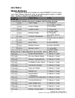
To discover the current file sizes of the above three files, read registers
112, 113 and 114 (see the Object Summary table in
). You need to
know the file size to avoid reading outside the bounds of the respective log file
(which will result in MODBUS errors).
Summary of Contents for Illuminator Supernova Series
Page 16: ...15 115895B System Installation Manual Figure 5 2 AC Connections for 6 25 k W 7 5 kW systems ...
Page 17: ...16 115895B System Installation Manual Figure 5 3 AC Connections for 10 kW 16 7 kW systems ...
Page 30: ...115895B System Installation Manual PART II OPTIONS MANUALS Section continues on next page ...
Page 95: ...94 115895B System Installation Manual SERIAL TO ETHERNET ADAPTER OPTION SECTION ...
Page 96: ...95 115895B System Installation Manual SERIAL TO ETHERNET ADAPTER OPTION SECTION ...
Page 114: ...113 115895B System Installation Manual DRAWINGS SECTION ...
Page 115: ...114 115895B System Installation Manual DRAWINGS SECTION ...
Page 116: ...115 115895B System Installation Manual DRAWINGS SECTION ...
Page 117: ...116 115895B System Installation Manual DRAWINGS SECTION ...
Page 118: ...117 115895B System Installation Manual DRAWINGS SECTION ...
Page 119: ...118 115895B System Installation Manual DRAWINGS SECTION ...
Page 120: ...119 115895B System Installation Manual DRAWINGS SECTION ...
Page 121: ...120 115895B System Installation Manual DRAWINGS SECTION ...
Page 122: ...121 115895B System Installation Manual DRAWINGS SECTION ...
Page 123: ...122 115895B System Installation Manual DRAWINGS SECTION ...
Page 124: ...123 115895B System Installation Manual DRAWINGS SECTION ...
Page 125: ...124 115895B System Installation Manual DRAWINGS SECTION ...
Page 126: ...125 115895B System Installation Manual DRAWINGS SECTION ...
Page 127: ...126 115895B System Installation Manual DRAWINGS SECTION ...
Page 128: ...127 115895B System Installation Manual DRAWINGS SECTION ...
Page 129: ...128 115895B System Installation Manual DRAWINGS SECTION ...
Page 130: ...129 115895B System Installation Manual DRAWINGS SECTION ...
Page 131: ...130 115895B System Installation Manual Notes ...

