74
115895B System Installation Manual
MODBUS TCP & SNMP COMMUNICATION OPTION SECTION
SECTION 4
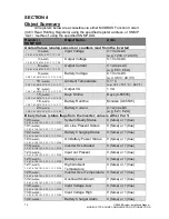
Object Summary
All registers below are accessible via either MODBUS Function Code 3
(0x03 Read Holding Registers) using the specified register address, or SNMP
‘Get’ / ‘Get Next’ using the specified SNMP OID.
Register /
SNMP OID
Object Name
Units
Analog Values (analog sensors or counters read from the inverter)
0
(0x0000)
1.3.6.1.4.1.3815.1.2.2.1.1.1.1.1.2.1
Input Voltage
0.1 Volts AC
(e.g. 1203 = 120.3V)
3
(0x0003)
1.3.6.1.4.1.3815.1.2.2.1.1.1.1.1.2.4
Output Voltage
0.1 Volts AC
6
(0x0006)
1.3.6.1.4.1.3815.1.2.2.1.1.1.1.1.2.7
Output Current
0.1 Amps AC
(e.g. 65 = 6.5A)
9
(0x0009)
1.3.6.1.4.1.3815.1.2.2.1.1.1.1.1.2.10
Battery Voltage
0.1 Volts DC
(e.g. 483 = 48.3 V)
10
(0x000A)
1.3.6.1.4.1.3815.1.2.2.1.1.1.1.1.2.11
Ambient Temperature
0.1 °C
(e.g. 301 = 30.1°C = 86.1°F)
12
(0x000C)
1.3.6.1.4.1.3815.1.2.2.1.1.1.1.1.2.13
Output VA
1 VA
15
(0x000F)
1.3.6.1.4.1.3815.1.2.2.1.1.1.1.1.2.16
Days Online
Days (0-65535)
16
(0x0010)
1.3.6.1.4.1.3815.1.2.2.1.1.1.1.1.2.17
Battery Runtime
Minutes (0-65535)
24
(0x0018)
1.3.6.1.4.1.3815.1.2.2.1.1.1.1.1.2.25
Battery Current
0.1 Amps DC
(e.g. 52 = 5.2A)
Binary Values (status flags from the inverter; value is either 0 or 1)
100
(0x0064)
1.3.6.1.4.1.3815.1.2.2.1.1.1.1.1.2.101
System Ready Status
0 (false) or 1 (true)
101
(0x0065)
1.3.6.1.4.1.3815.1.2.2.1.1.1.1.1.2.102
AC Line Present Status
0 (false) or 1 (true)
102
(0x0066)
1.3.6.1.4.1.3815.1.2.2.1.1.1.1.1.2.103
Battery Charging Status
0 (false) or 1 (true)
103
(0x0067)
1.3.6.1.4.1.3815.1.2.2.1.1.1.1.1.2.104
On Battery Power Status
0 (false) or 1 (true)
118
(0x0076)
1.3.6.1.4.1.3815.1.2.2.1.1.1.1.1.2.119
Inverter Overloaded
0 (false) or 1 (true)
123
(0x007B)
1.3.6.1.4.1.3815.1.2.2.1.1.1.1.1.2.124
Input not Present
0 (false) or 1 (true)
125
(0x007D)
1.3.6.1.4.1.3815.1.2.2.1.1.1.1.1.2.126
Battery Low
0 (false) or 1 (true)
127
(0x007F)
1.3.6.1.4.1.3815.1.2.2.1.1.1.1.1.2.128
High Ambient
Temperature
0 (false) or 1 (true)
129
(0x0081)
1.3.6.1.4.1.3815.1.2.2.1.1.1.1.1.2.130
Inverter Over Temperature 0 (false) or 1 (true)
132
(0x0084)
1.3.6.1.4.1.3815.1.2.2.1.1.1.1.1.2.133
Overload Shutdown
0 (false) or 1 (true)
138
(0x008A)
1.3.6.1.4.1.3815.1.2.2.1.1.1.1.1.2.139
Input Voltage Low
0 (false) or 1 (true)
139
(0x008B)
1.3.6.1.4.1.3815.1.2.2.1.1.1.1.1.2.140
Input Voltage High
0 (false) or 1 (true)
142
(0x008E)
Battery Charger Alarm
0 (false) or 1 (true)
Summary of Contents for Illuminator Supernova Series
Page 16: ...15 115895B System Installation Manual Figure 5 2 AC Connections for 6 25 k W 7 5 kW systems ...
Page 17: ...16 115895B System Installation Manual Figure 5 3 AC Connections for 10 kW 16 7 kW systems ...
Page 30: ...115895B System Installation Manual PART II OPTIONS MANUALS Section continues on next page ...
Page 95: ...94 115895B System Installation Manual SERIAL TO ETHERNET ADAPTER OPTION SECTION ...
Page 96: ...95 115895B System Installation Manual SERIAL TO ETHERNET ADAPTER OPTION SECTION ...
Page 114: ...113 115895B System Installation Manual DRAWINGS SECTION ...
Page 115: ...114 115895B System Installation Manual DRAWINGS SECTION ...
Page 116: ...115 115895B System Installation Manual DRAWINGS SECTION ...
Page 117: ...116 115895B System Installation Manual DRAWINGS SECTION ...
Page 118: ...117 115895B System Installation Manual DRAWINGS SECTION ...
Page 119: ...118 115895B System Installation Manual DRAWINGS SECTION ...
Page 120: ...119 115895B System Installation Manual DRAWINGS SECTION ...
Page 121: ...120 115895B System Installation Manual DRAWINGS SECTION ...
Page 122: ...121 115895B System Installation Manual DRAWINGS SECTION ...
Page 123: ...122 115895B System Installation Manual DRAWINGS SECTION ...
Page 124: ...123 115895B System Installation Manual DRAWINGS SECTION ...
Page 125: ...124 115895B System Installation Manual DRAWINGS SECTION ...
Page 126: ...125 115895B System Installation Manual DRAWINGS SECTION ...
Page 127: ...126 115895B System Installation Manual DRAWINGS SECTION ...
Page 128: ...127 115895B System Installation Manual DRAWINGS SECTION ...
Page 129: ...128 115895B System Installation Manual DRAWINGS SECTION ...
Page 130: ...129 115895B System Installation Manual DRAWINGS SECTION ...
Page 131: ...130 115895B System Installation Manual Notes ...


