7
115895B System Installation Manual
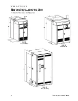
Table 3.1 Dimensions
Unit #1 (1.75-5.0KVA)
Unit
Depth (A)
Height
(B)
Width (C)
(D)
(E)
(F)
(G)
(H)
Cabinet
25”
48”
24”
44.75”
(113.6 cm)
22.13”
2.06”
2.38”
3.38”
(63.5 cm)
(61.0 cm)
(60.9 cm)
(56.2 cm)
(5.2 cm)
(6.0 cm)
(8.6 cm)
Extended
Height
56.3"
53.8
Option
(143 cm)
(136.7 cm)
Unit #2 (6.25-7.5KVA)
Unit
Depth
(A)
Height
(B)
Width
(C)
(D)
(E)
(F)
(G)
(H)
Cabinet
25”
53”
36”
50.5”
(128.3
cm)
34.18”
2.06”
2.38”
3.38”
(63.5 cm) (135.9 cm) (91.4 cm)
(86.8 cm)
(5.2 cm)
(6.0 cm)
(8.6 cm)
Extended
Height
61"
58.5"
Option
(155 cm)
(148.5
cm)
Unit #3 (10.0-16.7KVA)
Unit
Depth
(A)
Height
(B)
Width
(C)
(D)
(E)
(F)
(G)
(H)
Cabinet
25”
78.3”
42”
71.38”
(181.3
cm)
38.88”
6.38”
19.5”
4.5”
(63.5 cm)
(199 cm)
(106.7
cm)
(98.8 cm) (16.2 cm) (49.5 cm) (11.4 cm)
Table 3.2 Required Clearances
Sides
Top
Front
0”
(0.0 cm)
12”
(30.5 cm)
39”
(100.0 cm)
Table 3.3 Conduit Knockouts
Conduit Knockouts
Knockout holes are universally sized to accept
0.875
”, 1.0”, 1.75” & 2” across all unit
s (1.25KVA to 16.7KVA).
Summary of Contents for Illuminator Supernova Series
Page 16: ...15 115895B System Installation Manual Figure 5 2 AC Connections for 6 25 k W 7 5 kW systems ...
Page 17: ...16 115895B System Installation Manual Figure 5 3 AC Connections for 10 kW 16 7 kW systems ...
Page 30: ...115895B System Installation Manual PART II OPTIONS MANUALS Section continues on next page ...
Page 95: ...94 115895B System Installation Manual SERIAL TO ETHERNET ADAPTER OPTION SECTION ...
Page 96: ...95 115895B System Installation Manual SERIAL TO ETHERNET ADAPTER OPTION SECTION ...
Page 114: ...113 115895B System Installation Manual DRAWINGS SECTION ...
Page 115: ...114 115895B System Installation Manual DRAWINGS SECTION ...
Page 116: ...115 115895B System Installation Manual DRAWINGS SECTION ...
Page 117: ...116 115895B System Installation Manual DRAWINGS SECTION ...
Page 118: ...117 115895B System Installation Manual DRAWINGS SECTION ...
Page 119: ...118 115895B System Installation Manual DRAWINGS SECTION ...
Page 120: ...119 115895B System Installation Manual DRAWINGS SECTION ...
Page 121: ...120 115895B System Installation Manual DRAWINGS SECTION ...
Page 122: ...121 115895B System Installation Manual DRAWINGS SECTION ...
Page 123: ...122 115895B System Installation Manual DRAWINGS SECTION ...
Page 124: ...123 115895B System Installation Manual DRAWINGS SECTION ...
Page 125: ...124 115895B System Installation Manual DRAWINGS SECTION ...
Page 126: ...125 115895B System Installation Manual DRAWINGS SECTION ...
Page 127: ...126 115895B System Installation Manual DRAWINGS SECTION ...
Page 128: ...127 115895B System Installation Manual DRAWINGS SECTION ...
Page 129: ...128 115895B System Installation Manual DRAWINGS SECTION ...
Page 130: ...129 115895B System Installation Manual DRAWINGS SECTION ...
Page 131: ...130 115895B System Installation Manual Notes ...

