79
115895B System Installation Manual
MODBUS TCP & SNMP COMMUNICATION OPTION SECTION
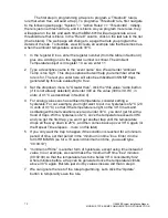
The first step in programming a trap is to program a
‘Threshold’ rule (a
rule that when true, will send a trap). To program a
‘Threshold’ rule, first navigate
to the following web page:
“System” >> “Action Rules” >> “Thresholds” . Initially,
there is just one threshold rule, and it is blank. As you program more rules, they
will appear on the list, and each time the BB2-6010 will auto-generate a new
threshold rule that is blank. In the
“Rule #” column, click on the last rule in the list
(that is blank). The web page will change to a page that lets you program the
details of the rule. To illustrate, we will create an example rule that becomes true
when the ambient temperature exceeds 30°C.
1 In the
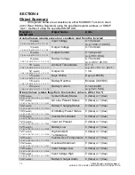
‘register #’ box, enter the register number (from the table in Section 4)
plus one. Adding one to the register number is critical. The Ambient
Temperature object is in register 10, so we enter 11.
2 Type a descriptive name in the
‘event name’ box. We will enter “Ambient
Temp is too high
”. This step is optional but will help you remember what the
rule is for. The text you enter here will also be embedded in SNMP traps
generated by this rule evaluating to
‘true’.
3 Set the dropdown menu to
“Greater than”, click the “this value:” radio button
(if it is not already selected) and enter 300 as the value (300 is 30.0°C, in
units of 0.1°C as described in Section 4)
4 For analog values such as ambient temperature, consider setting a
hysteresis. For our example, you might want to put in a hysteresis of 2°C (20
in units of 0.1°C) so that if the temperature is right on the 30°C mark and
oscillating with small variations over and under 30°C, you don
’t get hit with a
flood of traps. With a hysteresis of 2°C, once the temperature exceeds 30°C
and you get the first trap, you won
’t get another trap until the temperature
drops all the way down to 28°C, and then comes back up over 30°C again (or
the Repeat Time elapses
5 If you only want the trap to happen if the condition is reached for a minimum
period of time, set that period in the
“minimum on time” box. Enter it in the
form HH:MM:SS (so for a 10 second minimum on time, you would type
“00:00:10”)
6
“minimum off time” is another form of hysteresis, except using time instead of
value. In our example, we could make the
‘minimum off time’ be 2 minutes
(00:02:00) so that the temperature has to be below 30°C consistently for 2
whole minutes before a trap can be generated once the temperature climbs
above 30°C again. But lets just do it by value since we did that in step 4.
7 We can ignore the rest of the rule programming. Let
’s click the “Update”
button to temporarily save the rule.
Summary of Contents for Illuminator Supernova Series
Page 16: ...15 115895B System Installation Manual Figure 5 2 AC Connections for 6 25 k W 7 5 kW systems ...
Page 17: ...16 115895B System Installation Manual Figure 5 3 AC Connections for 10 kW 16 7 kW systems ...
Page 30: ...115895B System Installation Manual PART II OPTIONS MANUALS Section continues on next page ...
Page 95: ...94 115895B System Installation Manual SERIAL TO ETHERNET ADAPTER OPTION SECTION ...
Page 96: ...95 115895B System Installation Manual SERIAL TO ETHERNET ADAPTER OPTION SECTION ...
Page 114: ...113 115895B System Installation Manual DRAWINGS SECTION ...
Page 115: ...114 115895B System Installation Manual DRAWINGS SECTION ...
Page 116: ...115 115895B System Installation Manual DRAWINGS SECTION ...
Page 117: ...116 115895B System Installation Manual DRAWINGS SECTION ...
Page 118: ...117 115895B System Installation Manual DRAWINGS SECTION ...
Page 119: ...118 115895B System Installation Manual DRAWINGS SECTION ...
Page 120: ...119 115895B System Installation Manual DRAWINGS SECTION ...
Page 121: ...120 115895B System Installation Manual DRAWINGS SECTION ...
Page 122: ...121 115895B System Installation Manual DRAWINGS SECTION ...
Page 123: ...122 115895B System Installation Manual DRAWINGS SECTION ...
Page 124: ...123 115895B System Installation Manual DRAWINGS SECTION ...
Page 125: ...124 115895B System Installation Manual DRAWINGS SECTION ...
Page 126: ...125 115895B System Installation Manual DRAWINGS SECTION ...
Page 127: ...126 115895B System Installation Manual DRAWINGS SECTION ...
Page 128: ...127 115895B System Installation Manual DRAWINGS SECTION ...
Page 129: ...128 115895B System Installation Manual DRAWINGS SECTION ...
Page 130: ...129 115895B System Installation Manual DRAWINGS SECTION ...
Page 131: ...130 115895B System Installation Manual Notes ...


