80
115895B System Installation Manual
MODBUS TCP & SNMP COMMUNICATION OPTION SECTION
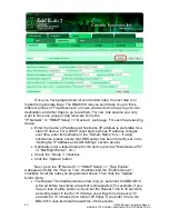
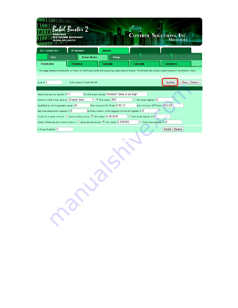
Once you have programmed all your desired rules, the next step is to
make them generate traps. The BB2-6010 lets you send traps to up to three
different groups of
“Trap Receivers” (in case you want some traps to go to one
destination, and other traps to go to another). For now, lets assume you only
want to have one group of trap receivers. Go to the
“IP Network” >> “SNMP Setup” >> “Devices”
web page. For each trap receiving
device:
•
Enter the device
’s IP address
or
hostname (IP address is preferable for a
static IP device. For a DHCP client device whose IP address changes
over time, enter its hostname in the
“Domain Name” box – if using
hostnames, please ensure that DNS server has been correctly set in the
“Setting Up IP Address and LAN Settings” section above)
•
Optionally enter a textual name for the device (such as
“Maintenance PC”
or
“Net Mgmt Server”, etc.)
•
Check the
“Group 1” checkbox
•
Click the
“Update” button
Next, go to the
“IP Network” >> “SNMP Setup” >> “Trap Enable”
webpage and click the
“Trap on True” checkbox and the “Enable Group 1”
checkbox for all the rules you programmed above. Then click the
“Update”
button. Note:
•
The Repeat Time field determines how long (in
‘seconds’) the BB2-6010
will wait before resending a trap that is still asserted. For example, if you
trap on loss of utility power, and you set the Repeat Time to 30 seconds,
and utility power is lost for 10 minutes, you will get one trap every 30
seconds for 10 minutes (for a total of 20 traps). If you enter 0 here, the
BB2-6010 uses its default repeat time of 60 seconds.
Summary of Contents for Illuminator Supernova Series
Page 16: ...15 115895B System Installation Manual Figure 5 2 AC Connections for 6 25 k W 7 5 kW systems ...
Page 17: ...16 115895B System Installation Manual Figure 5 3 AC Connections for 10 kW 16 7 kW systems ...
Page 30: ...115895B System Installation Manual PART II OPTIONS MANUALS Section continues on next page ...
Page 95: ...94 115895B System Installation Manual SERIAL TO ETHERNET ADAPTER OPTION SECTION ...
Page 96: ...95 115895B System Installation Manual SERIAL TO ETHERNET ADAPTER OPTION SECTION ...
Page 114: ...113 115895B System Installation Manual DRAWINGS SECTION ...
Page 115: ...114 115895B System Installation Manual DRAWINGS SECTION ...
Page 116: ...115 115895B System Installation Manual DRAWINGS SECTION ...
Page 117: ...116 115895B System Installation Manual DRAWINGS SECTION ...
Page 118: ...117 115895B System Installation Manual DRAWINGS SECTION ...
Page 119: ...118 115895B System Installation Manual DRAWINGS SECTION ...
Page 120: ...119 115895B System Installation Manual DRAWINGS SECTION ...
Page 121: ...120 115895B System Installation Manual DRAWINGS SECTION ...
Page 122: ...121 115895B System Installation Manual DRAWINGS SECTION ...
Page 123: ...122 115895B System Installation Manual DRAWINGS SECTION ...
Page 124: ...123 115895B System Installation Manual DRAWINGS SECTION ...
Page 125: ...124 115895B System Installation Manual DRAWINGS SECTION ...
Page 126: ...125 115895B System Installation Manual DRAWINGS SECTION ...
Page 127: ...126 115895B System Installation Manual DRAWINGS SECTION ...
Page 128: ...127 115895B System Installation Manual DRAWINGS SECTION ...
Page 129: ...128 115895B System Installation Manual DRAWINGS SECTION ...
Page 130: ...129 115895B System Installation Manual DRAWINGS SECTION ...
Page 131: ...130 115895B System Installation Manual Notes ...

