84
115895B System Installation Manual
SERIAL TO ETHERNET ADAPTER OPTION SECTION
INTRODUCTION
This manual is intended to explain the operation of the serial communication protocol for the
Illuminator Supernova Emergency Lighting Central Inverter. Serial Communication can be
established by means of a computer using terminal emulation software (such as Tera Term,
PuTTy, xterm, etc.), or by any embedded device capable of RS-232 serial communication. We
shall call this device the Client.
The protocol used is proprietary, and specific to Myers EPS
’ Emergency Lighting Central
Inverters.
CONNECTION
The Central Inverter has a 9-pin Sub-D (DB9) female connector typically located on the back
(inside) of the front display panel located on the door of the inverter. See below for the exact
location of the connector.
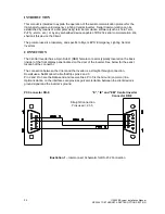
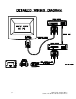
The connection between the Client and the Inverter is a straight-through connection.
Do
not
use a Null Modem Cable that flips pins 2 and 3.
Pin 2 and Pin 3 are the Data send and receive lines; Pin 5 is the Ground (common) line.
Optical isolation on the interface card provides galvanic isolation between the
client device’s
ground signal and the inverter
’s ground.
PC Connector DB-9
“E”, “IE” and “EM” Central Inverter
Connector DB-9
Straight Connection
Pins used = 2,3 5
Illustration 1
– Interconnect Schematic for RS-232 Connection
Summary of Contents for Illuminator Supernova Series
Page 16: ...15 115895B System Installation Manual Figure 5 2 AC Connections for 6 25 k W 7 5 kW systems ...
Page 17: ...16 115895B System Installation Manual Figure 5 3 AC Connections for 10 kW 16 7 kW systems ...
Page 30: ...115895B System Installation Manual PART II OPTIONS MANUALS Section continues on next page ...
Page 95: ...94 115895B System Installation Manual SERIAL TO ETHERNET ADAPTER OPTION SECTION ...
Page 96: ...95 115895B System Installation Manual SERIAL TO ETHERNET ADAPTER OPTION SECTION ...
Page 114: ...113 115895B System Installation Manual DRAWINGS SECTION ...
Page 115: ...114 115895B System Installation Manual DRAWINGS SECTION ...
Page 116: ...115 115895B System Installation Manual DRAWINGS SECTION ...
Page 117: ...116 115895B System Installation Manual DRAWINGS SECTION ...
Page 118: ...117 115895B System Installation Manual DRAWINGS SECTION ...
Page 119: ...118 115895B System Installation Manual DRAWINGS SECTION ...
Page 120: ...119 115895B System Installation Manual DRAWINGS SECTION ...
Page 121: ...120 115895B System Installation Manual DRAWINGS SECTION ...
Page 122: ...121 115895B System Installation Manual DRAWINGS SECTION ...
Page 123: ...122 115895B System Installation Manual DRAWINGS SECTION ...
Page 124: ...123 115895B System Installation Manual DRAWINGS SECTION ...
Page 125: ...124 115895B System Installation Manual DRAWINGS SECTION ...
Page 126: ...125 115895B System Installation Manual DRAWINGS SECTION ...
Page 127: ...126 115895B System Installation Manual DRAWINGS SECTION ...
Page 128: ...127 115895B System Installation Manual DRAWINGS SECTION ...
Page 129: ...128 115895B System Installation Manual DRAWINGS SECTION ...
Page 130: ...129 115895B System Installation Manual DRAWINGS SECTION ...
Page 131: ...130 115895B System Installation Manual Notes ...

