40
115895B System Installation Manual
BACNET IP & SNMP COMMUNICATION OPTION SECTION
SECTION 2
Description of Operation
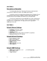
The single-phase Illuminator Supernova Emergency Lighting Central
Inverter acts as a BACnet IP server, and SNMP Agent (server).
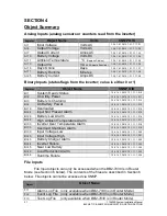
It supports a total of
nine
analog objects (floating point on BACnet IP, and
rounded to the nearest integer on SNMP),
seventeen
binary flag objects and
three
file objects (only accessible when BB2-7030 is in Router Mode).
It can also be programmed to transmit SNMP
‘traps’ when a programmed
condition is met (analog value goes above or below a threshold value, or binary
flag gets set to 1 or cleared to 0). The traps can be sent to specified IP
addresses on the LAN.
SECTION 3
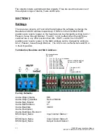
Default Ethernet Settings
•
IP Address:
10.0.0.101 (static)
•
Subnet Mask:
255.255.255.0
•
Gateway:
10.0.0.1
•
DHCP Client:
Turned off by default (but DHCP is supported)
•
Web Server Port:
80 (HTTP default)
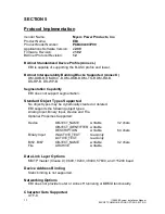
Default BACnet IP Settings
•
Device Instance
: 20800
•
Port
: 47808 (0xBAC0)
•
BACnet Router
: Disabled
•
BBMD
: Disabled
•
APDU Timeout
: 3 seconds
•
APDU Retries
: 3
Default SNMP Settings
•
SNMP Version Support
: v1, v2c (v3 is
not
supported)
•
Community
: public
•
Traps
: Disabled
Summary of Contents for Illuminator Supernova Series
Page 16: ...15 115895B System Installation Manual Figure 5 2 AC Connections for 6 25 k W 7 5 kW systems ...
Page 17: ...16 115895B System Installation Manual Figure 5 3 AC Connections for 10 kW 16 7 kW systems ...
Page 30: ...115895B System Installation Manual PART II OPTIONS MANUALS Section continues on next page ...
Page 95: ...94 115895B System Installation Manual SERIAL TO ETHERNET ADAPTER OPTION SECTION ...
Page 96: ...95 115895B System Installation Manual SERIAL TO ETHERNET ADAPTER OPTION SECTION ...
Page 114: ...113 115895B System Installation Manual DRAWINGS SECTION ...
Page 115: ...114 115895B System Installation Manual DRAWINGS SECTION ...
Page 116: ...115 115895B System Installation Manual DRAWINGS SECTION ...
Page 117: ...116 115895B System Installation Manual DRAWINGS SECTION ...
Page 118: ...117 115895B System Installation Manual DRAWINGS SECTION ...
Page 119: ...118 115895B System Installation Manual DRAWINGS SECTION ...
Page 120: ...119 115895B System Installation Manual DRAWINGS SECTION ...
Page 121: ...120 115895B System Installation Manual DRAWINGS SECTION ...
Page 122: ...121 115895B System Installation Manual DRAWINGS SECTION ...
Page 123: ...122 115895B System Installation Manual DRAWINGS SECTION ...
Page 124: ...123 115895B System Installation Manual DRAWINGS SECTION ...
Page 125: ...124 115895B System Installation Manual DRAWINGS SECTION ...
Page 126: ...125 115895B System Installation Manual DRAWINGS SECTION ...
Page 127: ...126 115895B System Installation Manual DRAWINGS SECTION ...
Page 128: ...127 115895B System Installation Manual DRAWINGS SECTION ...
Page 129: ...128 115895B System Installation Manual DRAWINGS SECTION ...
Page 130: ...129 115895B System Installation Manual DRAWINGS SECTION ...
Page 131: ...130 115895B System Installation Manual Notes ...

