56
115895B System Installation Manual
MODBUS SERIAL COMMUNICATION OPTION SECTION
SECTION 2
Description of Operation
The MODBUS Communication Option Board acts as a MODBUS slave. It
supports both the RTU (binary) and ASCII modes of MODBUS Over Serial Line.
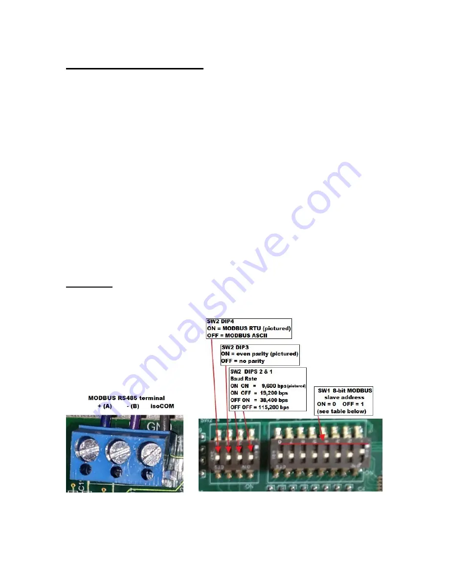
For both modes, it supports either Even Parity or No Parity, and four baud rates:
9600bps, 19,200bps, 38,400bps and 115,200bps. It supports being set to any
legal MODBUS slave address, between 1 and 247 (inclusive).
It supports a total of
twelve
16-bit analog objects (known as
‘holding
registers
’ in MODBUS),
sixteen
binary flag objects (known as
‘coils’ in MODBUS)
and
three
File Record objects. File Records are used to access one of three
dynamic logs of Alarms, Tests and Events.
The MODBUS Communication Option Board also supports the MODBUS
“Report Server ID” self-identification command, reporting its model number and
firmware revision in an ASCII string. You can also program a User ID up to 32
bytes long (in ASCII) that will be appended to the end of the self-identification
string.
SECTION 3
Settings
RS-485 connection, Serial Mode, Parity, Baudrate and Slave Address
:
Summary of Contents for Illuminator Supernova Series
Page 16: ...15 115895B System Installation Manual Figure 5 2 AC Connections for 6 25 k W 7 5 kW systems ...
Page 17: ...16 115895B System Installation Manual Figure 5 3 AC Connections for 10 kW 16 7 kW systems ...
Page 30: ...115895B System Installation Manual PART II OPTIONS MANUALS Section continues on next page ...
Page 95: ...94 115895B System Installation Manual SERIAL TO ETHERNET ADAPTER OPTION SECTION ...
Page 96: ...95 115895B System Installation Manual SERIAL TO ETHERNET ADAPTER OPTION SECTION ...
Page 114: ...113 115895B System Installation Manual DRAWINGS SECTION ...
Page 115: ...114 115895B System Installation Manual DRAWINGS SECTION ...
Page 116: ...115 115895B System Installation Manual DRAWINGS SECTION ...
Page 117: ...116 115895B System Installation Manual DRAWINGS SECTION ...
Page 118: ...117 115895B System Installation Manual DRAWINGS SECTION ...
Page 119: ...118 115895B System Installation Manual DRAWINGS SECTION ...
Page 120: ...119 115895B System Installation Manual DRAWINGS SECTION ...
Page 121: ...120 115895B System Installation Manual DRAWINGS SECTION ...
Page 122: ...121 115895B System Installation Manual DRAWINGS SECTION ...
Page 123: ...122 115895B System Installation Manual DRAWINGS SECTION ...
Page 124: ...123 115895B System Installation Manual DRAWINGS SECTION ...
Page 125: ...124 115895B System Installation Manual DRAWINGS SECTION ...
Page 126: ...125 115895B System Installation Manual DRAWINGS SECTION ...
Page 127: ...126 115895B System Installation Manual DRAWINGS SECTION ...
Page 128: ...127 115895B System Installation Manual DRAWINGS SECTION ...
Page 129: ...128 115895B System Installation Manual DRAWINGS SECTION ...
Page 130: ...129 115895B System Installation Manual DRAWINGS SECTION ...
Page 131: ...130 115895B System Installation Manual Notes ...

