60
115895B System Installation Manual
MODBUS SERIAL COMMUNICATION OPTION SECTION
SECTION 4
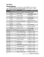
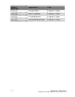
Object Summary (Registers and Coils)
The sixteen-bit registers can be accessed via either MODBUS Function
Code 3 (0x03 Read Holding Registers) or Function Code 4 (0x04 Read Input
Registers). Results will be identical.
The flag objects can be accessed via either MODBUS Function Code 1
(0x01 Read Coils) or Function Code 2 (0x02 Read Discrete Inputs). Results will
be identical.
All objects are read-only; no MODBUS write commands are supported.
Register
Object Name
Units
0
(0x0000)
Input Voltage
0.1 Volts AC (e.g. 1203 = 120.3V)
3
(0x0003)
Output Voltage
0.1 Volts AC
6
(0x0006)
Output Current
0.1 Amps AC (e.g. 461 = 46.1A)
9
(0x0009)
Battery Voltage
0.1 Volts DC (e.g. 483 = 48.3 V)
10
(0x000A)
Ambient Temperature
0.1 °C (e.g. 301 = 30.1°C = 86.1°F)
12
(0x000C)
Output VA
1 VA (e.g. 10000 = 10kVA)
15
(0x000F)
Days Online
Days (0-65535)
16
(0x0010)
Battery Runtime
Minutes (0-65535)
24
(0x0018)
Battery Current
0.1 Amps DC (e.g. 52 = 5.2A)
152
(0x0098)
Alarm Log File Size
Bytes (0-65535)
153
(0x0099)
Event Log File Size
Bytes (0-65535)
154
(0x009A)
Test Log File Size
Bytes (0-65535)
Coil
Object Name
Values
0
(0x0000)
System Ready Status
1 = ready, 0 = not ready
1
(0x0001)
AC Line Present Status
1 = present, 0 = not present
2
(0x0002)
Battery Charging Status
1 = charging, 0 = not charging
3
(0x0003)
On Battery Power Status
1 = battery power, 0 = line power
18
(0x0012)
Overload
1 = alarm, 0 = normal
23
(0x0017)
Input not Present
1 = alarm, 0 = normal
25
(0x0019)
Battery Low
1 = alarm, 0 = normal
27
(0x001B)
High Ambient Temperature
1 = alarm, 0 = normal
29
(0x001D)
Over Temperature
1 = alarm, 0 = normal
32
(0x0020)
Overload Shutdown
1 = alarm, 0 = normal
38
(0x0026)
Input Voltage Low
1 = alarm, 0 = normal
39
(0x0027)
Input Voltage High
1 = alarm, 0 = normal
42
(0x002A)
Battery Charger
1 = alarm, 0 = normal
43
(0x002B)
Inverter Failure
1 = alarm, 0 = normal
44
(0x002C)
Near Low Battery
1 = alarm, 0 = normal
45
(0x002D)
Load Reduction
1 = alarm, 0 = normal
47
(0x002F)
Runtime Failure
1 = alarm, 0 = normal
Summary of Contents for Illuminator Supernova Series
Page 16: ...15 115895B System Installation Manual Figure 5 2 AC Connections for 6 25 k W 7 5 kW systems ...
Page 17: ...16 115895B System Installation Manual Figure 5 3 AC Connections for 10 kW 16 7 kW systems ...
Page 30: ...115895B System Installation Manual PART II OPTIONS MANUALS Section continues on next page ...
Page 95: ...94 115895B System Installation Manual SERIAL TO ETHERNET ADAPTER OPTION SECTION ...
Page 96: ...95 115895B System Installation Manual SERIAL TO ETHERNET ADAPTER OPTION SECTION ...
Page 114: ...113 115895B System Installation Manual DRAWINGS SECTION ...
Page 115: ...114 115895B System Installation Manual DRAWINGS SECTION ...
Page 116: ...115 115895B System Installation Manual DRAWINGS SECTION ...
Page 117: ...116 115895B System Installation Manual DRAWINGS SECTION ...
Page 118: ...117 115895B System Installation Manual DRAWINGS SECTION ...
Page 119: ...118 115895B System Installation Manual DRAWINGS SECTION ...
Page 120: ...119 115895B System Installation Manual DRAWINGS SECTION ...
Page 121: ...120 115895B System Installation Manual DRAWINGS SECTION ...
Page 122: ...121 115895B System Installation Manual DRAWINGS SECTION ...
Page 123: ...122 115895B System Installation Manual DRAWINGS SECTION ...
Page 124: ...123 115895B System Installation Manual DRAWINGS SECTION ...
Page 125: ...124 115895B System Installation Manual DRAWINGS SECTION ...
Page 126: ...125 115895B System Installation Manual DRAWINGS SECTION ...
Page 127: ...126 115895B System Installation Manual DRAWINGS SECTION ...
Page 128: ...127 115895B System Installation Manual DRAWINGS SECTION ...
Page 129: ...128 115895B System Installation Manual DRAWINGS SECTION ...
Page 130: ...129 115895B System Installation Manual DRAWINGS SECTION ...
Page 131: ...130 115895B System Installation Manual Notes ...

