86
115895B System Installation Manual
SERIAL TO ETHERNET ADAPTER OPTION SECTION
Help screen
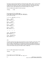
You
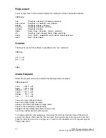
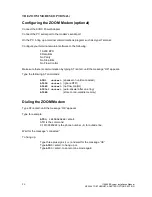
may type “help” at the command prompt for a listing of various commands available.
CMD>help
ver Display current firmware version.
set point Display or modify set points.
meter Display meter values.
status Display present status.
alarms Display alarms.
dump Dump logs (alarms, tests, events).
dt Display and change date-time setting.
help List shell commands with brief descriptions.
exit Exit from shell.
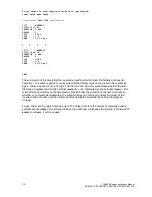
Version
The Revision level of the so
ftware is available by the “ver” command.
CMD>ver
IF: 2.08
FP: 1.02
CMD>
Alarm Setpoint
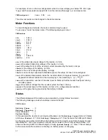
When the set point command is entered the following data is displayed:
CMD>setpoint
lvac : 108.0 off
hvac : 132.0 off
nlbatt: 111.0 off
lbatt : 105.0 off
htemp : 45.0 on
lrc : 0.0 off
lvac
is the Low Voltage AC alarm,
hvac
is the High Voltage AC alarm,
nlbatt
is the Near Low Battery Voltage alarm,
lbatt
is the Low Battery Voltage Alarm,
htemp
is the High temperature alarm set point, and
lrc
is the Load Reduction Fault set point.
To change a setpoint, type
‘
setpoint
’, then press the ‘tab’ key, then the name of the setpoint
you wish to change, then press
the ‘tab’ key again, then type the new value you wish to set, then
press the ‘tab’ key once more, and type ‘
on
’ or ‘
off
’ (to turn the alarm on or off respectively) and
finally press ‘enter’.
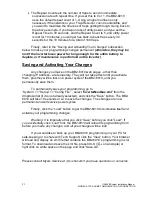
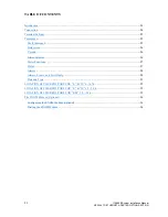
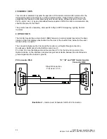
Summary of Contents for Illuminator Supernova Series
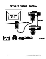
Page 16: ...15 115895B System Installation Manual Figure 5 2 AC Connections for 6 25 k W 7 5 kW systems ...
Page 17: ...16 115895B System Installation Manual Figure 5 3 AC Connections for 10 kW 16 7 kW systems ...
Page 30: ...115895B System Installation Manual PART II OPTIONS MANUALS Section continues on next page ...
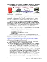
Page 95: ...94 115895B System Installation Manual SERIAL TO ETHERNET ADAPTER OPTION SECTION ...
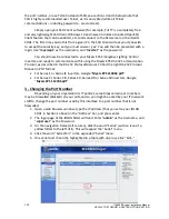
Page 96: ...95 115895B System Installation Manual SERIAL TO ETHERNET ADAPTER OPTION SECTION ...
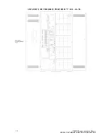
Page 114: ...113 115895B System Installation Manual DRAWINGS SECTION ...
Page 115: ...114 115895B System Installation Manual DRAWINGS SECTION ...
Page 116: ...115 115895B System Installation Manual DRAWINGS SECTION ...
Page 117: ...116 115895B System Installation Manual DRAWINGS SECTION ...
Page 118: ...117 115895B System Installation Manual DRAWINGS SECTION ...
Page 119: ...118 115895B System Installation Manual DRAWINGS SECTION ...
Page 120: ...119 115895B System Installation Manual DRAWINGS SECTION ...
Page 121: ...120 115895B System Installation Manual DRAWINGS SECTION ...
Page 122: ...121 115895B System Installation Manual DRAWINGS SECTION ...
Page 123: ...122 115895B System Installation Manual DRAWINGS SECTION ...
Page 124: ...123 115895B System Installation Manual DRAWINGS SECTION ...
Page 125: ...124 115895B System Installation Manual DRAWINGS SECTION ...
Page 126: ...125 115895B System Installation Manual DRAWINGS SECTION ...
Page 127: ...126 115895B System Installation Manual DRAWINGS SECTION ...
Page 128: ...127 115895B System Installation Manual DRAWINGS SECTION ...
Page 129: ...128 115895B System Installation Manual DRAWINGS SECTION ...
Page 130: ...129 115895B System Installation Manual DRAWINGS SECTION ...
Page 131: ...130 115895B System Installation Manual Notes ...

