87
115895B System Installation Manual
SERIAL TO ETHERNET ADAPTER OPTION SECTION
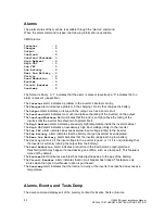
For example, to turn on the low voltage alarm when the input voltage goes below 105 VAC, type
“
lvac
” and then press tab and type”
105
” and then tab and then type “
on
” and press enter.
CMD>setpoint
lvac 105
on
The other set points can be changed in the same manner.
Meter Functions
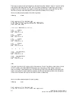
To read Voltages and currents, the meter command may be used.
To use, type, “meter” and press enter. The following display will occur.
CMD>meter
vin : 118.3
vout : 118.3
iout : 12.3
vbatt : 54.1
ibatt : 0.1
tbatt : -61.1
tint : 29.8
imin : 0
days : 0
vaout : 1453.8
iwatts : 6.6
vin
is the (utility side) input voltage to the inverter, in Volts.
vout
is the output (load side) voltage of the inverter, in Volts.
iout
is the output current of the inverter (current consumed by the load), in Amps.
vbatt
is the voltage of the battery, in Volts.
ibatt
is the current through the battery, in Amps.
tbatt
is not currently supported in hardware. Ignore this value; for now it is meaningless.
tint
is the ambient temperature inside the inverter cabinet, in degrees Celsius. To convert to
degrees Fahrenheit, subtract 32, then multiply by 5, then divide by 9.
imin
is the cumulative ‘number of minutes’ (over its lifetime) that the inverter has spent running
on battery power.
days
is the number of days that the inverter system has been running
vaout
is the output power of the inverter, in Vars (VA
– voltage ampere reactive).
iwatts
is the power being provided by the battery, in Watts.
Status
The different statuses of the machine are accessible by typing
“status” and enter.
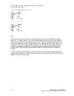
The following message occurs when status command is sent:
CMD>status
Battery Power : 0
Battery Charging: 1
Line Present : 1
System Ready : 1
In this example, the inverter is running on utility power, so the
Battery Power
status is 0 (false)
and
Line Present
is 1 (true).
Battery Charging
is 1 (true) because the battery will always
be charging, even when its full. When
the battery is full, the inverter uses ‘float-charging’ to keep
the battery full
– this only consumes a tiny amount of power (in the ‘meter’ example above, it is
shown consuming 6.6W as it float-charges). Finally,
System Ready
is 1 (true). This will always
be the case unless the inverter is rebooting, on battery power, or charging.
Summary of Contents for Illuminator Supernova Series
Page 16: ...15 115895B System Installation Manual Figure 5 2 AC Connections for 6 25 k W 7 5 kW systems ...
Page 17: ...16 115895B System Installation Manual Figure 5 3 AC Connections for 10 kW 16 7 kW systems ...
Page 30: ...115895B System Installation Manual PART II OPTIONS MANUALS Section continues on next page ...
Page 95: ...94 115895B System Installation Manual SERIAL TO ETHERNET ADAPTER OPTION SECTION ...
Page 96: ...95 115895B System Installation Manual SERIAL TO ETHERNET ADAPTER OPTION SECTION ...
Page 114: ...113 115895B System Installation Manual DRAWINGS SECTION ...
Page 115: ...114 115895B System Installation Manual DRAWINGS SECTION ...
Page 116: ...115 115895B System Installation Manual DRAWINGS SECTION ...
Page 117: ...116 115895B System Installation Manual DRAWINGS SECTION ...
Page 118: ...117 115895B System Installation Manual DRAWINGS SECTION ...
Page 119: ...118 115895B System Installation Manual DRAWINGS SECTION ...
Page 120: ...119 115895B System Installation Manual DRAWINGS SECTION ...
Page 121: ...120 115895B System Installation Manual DRAWINGS SECTION ...
Page 122: ...121 115895B System Installation Manual DRAWINGS SECTION ...
Page 123: ...122 115895B System Installation Manual DRAWINGS SECTION ...
Page 124: ...123 115895B System Installation Manual DRAWINGS SECTION ...
Page 125: ...124 115895B System Installation Manual DRAWINGS SECTION ...
Page 126: ...125 115895B System Installation Manual DRAWINGS SECTION ...
Page 127: ...126 115895B System Installation Manual DRAWINGS SECTION ...
Page 128: ...127 115895B System Installation Manual DRAWINGS SECTION ...
Page 129: ...128 115895B System Installation Manual DRAWINGS SECTION ...
Page 130: ...129 115895B System Installation Manual DRAWINGS SECTION ...
Page 131: ...130 115895B System Installation Manual Notes ...

