88
115895B System Installation Manual
SERIAL TO ETHERNET ADAPTER OPTION SECTION
Alarms
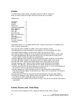
The alarm status of the m
achine is available through the “alarms” command.
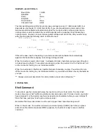
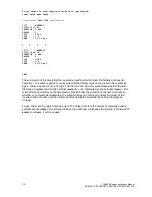
When the alarm command is typed, the following information is available.
CMD>alarms
Inverter : 0
Charger : 0
Output : 0
Overload : 0
Overload Shutdown: 0
High Ambient : 0
High VAC : 0
Low VAC : 0
Low Battery : 0
Near Low Battery : 0
Utility : 0
Load Reduction : 0
Runtime : 0
Circuit Breaker : 0
Overtemp : 0
The format is binary. A “1” indicates that the alarm is present (asserted); a “0” indicates that no
alarm is present (unasserted).
The
Inverter
alarm i
ndicates a problem in the inverter’s internal circuitry.
The
Charger
alarm indicates a problem in the charging circuitry that charges the battery.
The
Output
alarm indicates an issue with the output, such as a short circuit.
The
Overload
alarm indicates too much load (above the rating of the inverter) on the output.
The
Overload
Shutdown
alarm indicates that the load is so high (above the rating of the
inverter) that the inverter has shutdown to protect itself.
The
High Ambient
alarm indicates excessively high temperature inside the inverter cabinet.
The
High VAC
alarm indicates an excessively high input voltage (utility) to the inverter.
The
Low VAC
alarm indicates an excessively low input voltage (utility) to the inverter.
The
Low Battery
alarm indicates that the battery charge has almost been depleted.
The
Near Low Battery
alarm indicates that the inverter is approaching low battery.
The
Utility
alarm is 0 if the input voltage to the inverter is good, or 1 if it is not (indicating that
the inverter is currently running the output from the battery).
The
Load Reduction
alarm indicates a reduction in the load below a preprogrammed
threshold (which may happen if a load device goes offline, such as a lamp out). This feature is
turned off by default.
The
Runtime
alarm indicates a self-test has failed (perhaps due to the age of the battery).
The
Circuit Breaker
alarm indicates that a circuit breaker has tripped. This feature only
works when the right circuit breaker option is purchased.
The
Overtemp
alarm indicates that the internal circuitry of the inverter has reached an excessive
temperature.
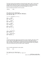
Alarms, Events, and Tests Dump
The dump command displays all of the memory content for Events, Tests or Alarms.
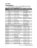
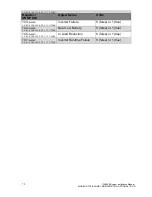
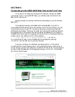
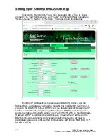
Summary of Contents for Illuminator Supernova Series
Page 16: ...15 115895B System Installation Manual Figure 5 2 AC Connections for 6 25 k W 7 5 kW systems ...
Page 17: ...16 115895B System Installation Manual Figure 5 3 AC Connections for 10 kW 16 7 kW systems ...
Page 30: ...115895B System Installation Manual PART II OPTIONS MANUALS Section continues on next page ...
Page 95: ...94 115895B System Installation Manual SERIAL TO ETHERNET ADAPTER OPTION SECTION ...
Page 96: ...95 115895B System Installation Manual SERIAL TO ETHERNET ADAPTER OPTION SECTION ...
Page 114: ...113 115895B System Installation Manual DRAWINGS SECTION ...
Page 115: ...114 115895B System Installation Manual DRAWINGS SECTION ...
Page 116: ...115 115895B System Installation Manual DRAWINGS SECTION ...
Page 117: ...116 115895B System Installation Manual DRAWINGS SECTION ...
Page 118: ...117 115895B System Installation Manual DRAWINGS SECTION ...
Page 119: ...118 115895B System Installation Manual DRAWINGS SECTION ...
Page 120: ...119 115895B System Installation Manual DRAWINGS SECTION ...
Page 121: ...120 115895B System Installation Manual DRAWINGS SECTION ...
Page 122: ...121 115895B System Installation Manual DRAWINGS SECTION ...
Page 123: ...122 115895B System Installation Manual DRAWINGS SECTION ...
Page 124: ...123 115895B System Installation Manual DRAWINGS SECTION ...
Page 125: ...124 115895B System Installation Manual DRAWINGS SECTION ...
Page 126: ...125 115895B System Installation Manual DRAWINGS SECTION ...
Page 127: ...126 115895B System Installation Manual DRAWINGS SECTION ...
Page 128: ...127 115895B System Installation Manual DRAWINGS SECTION ...
Page 129: ...128 115895B System Installation Manual DRAWINGS SECTION ...
Page 130: ...129 115895B System Installation Manual DRAWINGS SECTION ...
Page 131: ...130 115895B System Installation Manual Notes ...

