96
115895B System Installation Manual
SERIAL TO ETHERNET ADAPTER OPTION SECTION
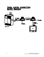
THE ZOOM MODEM (OPTIONAL)
Configuring the ZOOM Modem (optional)
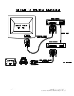
Connect the 9VDC Power Adapter
Connect the PC serial port to the modem
’s serial port
On the PC, bring up a terminal communications program such as HyperTerminal.
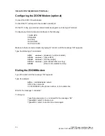
Configure your terminal emulator software to the following:
19,200 BPS
8 Data Bits
No Parity
No Stop Bits
No Flow Control
Make sure there is communication by typing AT<enter> until the message
“OK” appears.
Type the following AT commands:
ATM1 <enter>
(speaker on until connected)
AT&D0 <enter>
(ignore DTR)
AT&K0 <enter>
(no flow control)
ATS0=1 <enter>
(auto-answer after one ring)
AT&W0
(store to non-volatile memory)
Dialing the ZOOM Modem
Type AT<enter>
until the message “OK” appears
Type for example:
ATD9, 16109545224
<enter>
ATD is the command
9,16109545224 is the phone number
–9, for outside line.
Wait for the mes
sage “connected”
To hang up:
Type three plus signs (+++) and wait for t
he message “OK”
Type
ATH0
<enter> to hang up or,
Type
ATO0
<enter> to enter online mode again
Summary of Contents for Illuminator Supernova Series
Page 16: ...15 115895B System Installation Manual Figure 5 2 AC Connections for 6 25 k W 7 5 kW systems ...
Page 17: ...16 115895B System Installation Manual Figure 5 3 AC Connections for 10 kW 16 7 kW systems ...
Page 30: ...115895B System Installation Manual PART II OPTIONS MANUALS Section continues on next page ...
Page 95: ...94 115895B System Installation Manual SERIAL TO ETHERNET ADAPTER OPTION SECTION ...
Page 96: ...95 115895B System Installation Manual SERIAL TO ETHERNET ADAPTER OPTION SECTION ...
Page 114: ...113 115895B System Installation Manual DRAWINGS SECTION ...
Page 115: ...114 115895B System Installation Manual DRAWINGS SECTION ...
Page 116: ...115 115895B System Installation Manual DRAWINGS SECTION ...
Page 117: ...116 115895B System Installation Manual DRAWINGS SECTION ...
Page 118: ...117 115895B System Installation Manual DRAWINGS SECTION ...
Page 119: ...118 115895B System Installation Manual DRAWINGS SECTION ...
Page 120: ...119 115895B System Installation Manual DRAWINGS SECTION ...
Page 121: ...120 115895B System Installation Manual DRAWINGS SECTION ...
Page 122: ...121 115895B System Installation Manual DRAWINGS SECTION ...
Page 123: ...122 115895B System Installation Manual DRAWINGS SECTION ...
Page 124: ...123 115895B System Installation Manual DRAWINGS SECTION ...
Page 125: ...124 115895B System Installation Manual DRAWINGS SECTION ...
Page 126: ...125 115895B System Installation Manual DRAWINGS SECTION ...
Page 127: ...126 115895B System Installation Manual DRAWINGS SECTION ...
Page 128: ...127 115895B System Installation Manual DRAWINGS SECTION ...
Page 129: ...128 115895B System Installation Manual DRAWINGS SECTION ...
Page 130: ...129 115895B System Installation Manual DRAWINGS SECTION ...
Page 131: ...130 115895B System Installation Manual Notes ...


