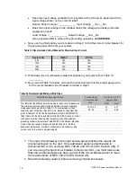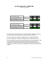
113903G -System Installation Manual
9
Inverter Module and Battery Module Assembly
Refer to Chapter 8 for Optional Wall Mounting directions.
5 x 8-32 screws located on the front and top of the module easily remove the
Inverter Module cover and 5 x 8-32 screws located on the front of the Battery
Module’s easily remove each cover. There are 4 holes located on each corner that
allow the ¼-20 hardware to attach to the different modules.
There are Electrical Knock-Outs that must be removed on the Inverter Module and
the Battery Module to allow passage of the battery cables. After the Electrical Knock-
Outs are removed, the factory provided plastic grommet must be inserted through
the hole to provide abrasion resistance for the wires. After the plastic grommet is
inserted, the bolts, washers and lock washers should be inserted and tightened
down. Use the plastic grommet as the alignment between the two modules. Shown
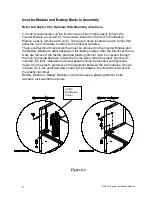
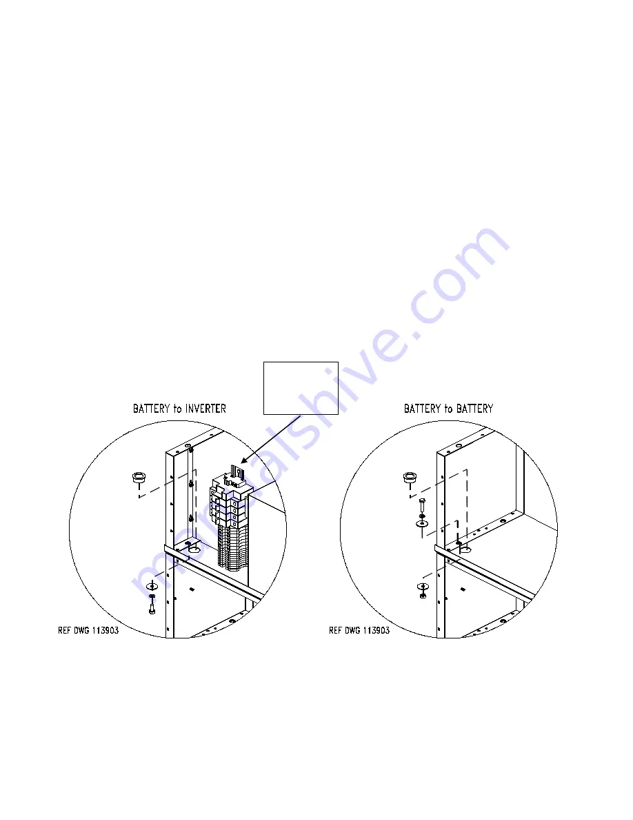
in figure 4.2 is the exploded view showing the hardware, Electrical Knock-Out and
the plastic Grommet.
Battery Module to Battery Module connections uses a plastic grommet, bolts,
washers, lock washers and nuts.
Figure 4.2
AC/DC
Distribution
Center


